|
WARNING: If you do any of these mods, DO NOT make the axle straight
unless it needs to be. Check the camber to make sure the wheels are at 0°!!!
The rear axle on the Rialta is a Winnebago supplied weldment that uses VW wheel
hubs and brake parts. With the use of just the single tire on the rear, the carrying
capacity is limited and thus the design of the rear axle does not anticipate any
overload conditions. Owners that have periodically overloaded the rear axle have
noticed some bowing or bending of the axle tube which causes excessive wear on the
inside edge of the rear tires. This can easily be measure by holding a metal straight
edge along either the top or bottom of the axle. An un-laden vehicle is supposed
to demonstrate a slight bow, up or down, which is the camber to the tube created during
the manufacturing process. This results in camber of 0° on the tires. The axle tubes are not supposed
to bend or bow to any appreciable extent under normal loading conditions but it
becomes clear that the Rialta's axle is the weakest link in the chain.
This modification proposes to remedy or avert the problem of the axle bending
and the problem of excessive wear on the inside edge of the rear tires by installing
angle iron or channel to provide additional strength and keep the axle from bowing
or bending under heavy load. This DOES NOT add any additional carrying capacity
and at best only helps maintain the structural integrity of the axle. While some
engineers have told me it may not do any good, nearly all have said that it can
do no harm.
Here are three such modifications done by Rialta owners:
Steel U-Channel Installation
This first installation used 3" wide steel U-channel but he failed to mention
the length of the legs on the U-channel. My guess is that the legs were 1-1/2" or
2". The steel channel is mounted to the bottom only of the axle and the round U-bolts
fit neatly over the top of the axle. The disadvantage of this method is that the
threaded portion of the U-bolts stick down and may reduce the ground clearance.
If the excess portions of the bolts are cut off, then they probably stick down no
farther than other items on the Rialta such as the sewer pipes, spare tires, etc.
From: Harry
Date: Mon Nov 29, 2004 9:54 pm
I completed my version of the
rear axle support or stiffening this weekend.
I used a 48" long piece of 3"
channel iron which I clamped to the axle with 5 - 9/16" X 3" U-bolts. The bolts
are spaced with one bolt in the center and two bolts on either side. I chose 5
rather than 6 bolts because I did not want to interfere with the brake line stand
offs. To help the channel set flat across the bottom of the axle I clipped off
the lower leg of each brake line stand off.
For cross straps I used five
5" sections of 2" channel iron with 9/16" holes drilled for the U-bolts.
I used the 2" channel for cross
straps because it is stronger than flat stock and gains additional thickness for
the axle / channel iron package. This additional thickness was necessary because
the ready made 9/16" U-bolts are not threaded far enough to allow ample clamping
action. I wanted to use 9/16" "U" bolts to insure sufficient rigidity when the
axle attempts to flex.
I also used hardened flat washers
to prevent the lock washers from distorting when in contact with the softer channel
iron when tension is applied. I tightened the U-bolts as tight as I could with
a 12" ratchet wrench.
I do not believe the change in
clearance between the axle and the ground will have any negative effects because
the wheels determine how low the axle can travel.
If any one has any questions
I will do my best to answer them.
Harry P.
98 RD
[ return to top ]
Steel Angle Installation
No pictures provided but this installation sounds nearly identical to the steel
u-channel installation except instead of using a heavy steel U-channel, an angle
iron shape is used instead. The angle iron fits under the bottom of the axle much
like a upside down "L" shape. The long 2" vertical leg of the angle iron provides
the stiffening required.
Bud, here are some particulars on the angle iron installation.
The angle iron is 2'' x 2'' size. The length is such that it extends fully across
the axle to the extent that each end reaches under the half cylinders that are
welded on the top of the axle. The "U" bolts are 3'' diameter by 6'' long. They
are just mild steel and I bought them at a hardware store. I made the bottom
clamps myself from 3/8' mild steel flat bar that is about an inch and a quarter
wide. The angle iron is placed on the bottom side of the axle. The "U" bolts
are placed on top of the half cylinders that are welded on top of the axle and
you can slip them in between the axle and the brake lines on the back side of
the axle. The angle iron is oriented such that one leg is flat along the bottom
of the axle with the other leg pointing down. This orientation puts the vertical
leg in tension when the axle tries to bow and thus the angle iron can never
bend itself and provides maximum force to resist bowing of the axle. At the
very end on each side of the vertical leg only on the angle iron cut off just
enough so that the "U" bolt clamps can be attached. Really, what to do is fairly
obvious and you shouldn't have any serious problems. GOOD LUCK!!
Bob
[ return to top ]
Stainless Steel Double U-channel Installation
The advantage of using this method is three-fold. First, the stainless steel
will never rust. Second, the "double-box" provides more stiffening than just a
single u-channel or angle iron. And third, the u-bolt brackets can be pointing
upward instead of downward thereby not creating any ground clearance problem.
Stainless steel was selected simply because it is stronger than regular steel
and has the added benefit of not rusting. I used a 2" wide x 1" high u-channel
along the top and bottom of the regular axle tube to provide a "boxed beam" design.
The bottom piece is 48 inches long whereas the top piece is 42" long, the difference
being the width rebound bumpers which can be seen just to the right of the top
piece of channel in the photo. There is one minor problem with using a u-channel
along the top: one small metal bracket that holds two brake lines is welded just
off the top left edge to the axle tube and it has to be cut or ground off to allow
the u-channel to fit. Once the u-channel is fitted in place, the bracket can be
re-welded in position or a product such as "J-B Weld" can be used to attach and
hold it in position. You can see this towards the far left side of the top piece
of u-channel.
 A
standard axle tube has an O.D. of 2-3/8" which is exactly what the Rialta has
so there are standard suspension u-bolts available made to precisely go over the
2-3/8" axle. Typically these are high strength steel rods with a diameter of either
3/8" or 1/2". There are even square shaped u-bolts that are available that would
have looked better on my double-channel "boxed beam" shape, but I could not find
any square shaped u-bolt in a stainless material so instead I opted to use the
regular round shape. Granted, it does not conform to the square shape of the u-channel
but once the bolts are tightened, the u-bolts do not slip and do not deform shape.
I used 3/8" diameter stainless steel u-bolts and torqued the stainless heavy hex
nuts to 40 ft/lbs. A stainless angle was used as the pressure plate and the extra
leg on the angle prevents the plate from bending down when the nuts are tightened.
Once the torque settings were accomplished, a jack nut was snugged up from the
underside of the angle plate to prevent any movement or distortion. The excess
length of the u-bolts can be cut off if desired, but I choose to leave them alone
as they are far from hitting anything even if the suspension system is completely
bottomed out. A
standard axle tube has an O.D. of 2-3/8" which is exactly what the Rialta has
so there are standard suspension u-bolts available made to precisely go over the
2-3/8" axle. Typically these are high strength steel rods with a diameter of either
3/8" or 1/2". There are even square shaped u-bolts that are available that would
have looked better on my double-channel "boxed beam" shape, but I could not find
any square shaped u-bolt in a stainless material so instead I opted to use the
regular round shape. Granted, it does not conform to the square shape of the u-channel
but once the bolts are tightened, the u-bolts do not slip and do not deform shape.
I used 3/8" diameter stainless steel u-bolts and torqued the stainless heavy hex
nuts to 40 ft/lbs. A stainless angle was used as the pressure plate and the extra
leg on the angle prevents the plate from bending down when the nuts are tightened.
Once the torque settings were accomplished, a jack nut was snugged up from the
underside of the angle plate to prevent any movement or distortion. The excess
length of the u-bolts can be cut off if desired, but I choose to leave them alone
as they are far from hitting anything even if the suspension system is completely
bottomed out.
Please note that these are all home made items and unless you live in a major
metropolitan area, you may have some difficulty in finding local sources for similar
materials in a stainless finish. Also be aware that there is a significant premium
cost increase for the stainless material over the regular steel. You may wish
to contact a specialty plumbing or pipe-fitting contractor that specializes in
such jobs as dairies, food processing plants, etc. You won't find this type of
material at your local hardware store or even Home Depot or Lowe's.
Installation by Baldy, 2000 HD, August 2005
| |
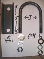
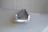 Here's
an end view of the stainless u-channel used. Here's
an end view of the stainless u-channel used. |
| |
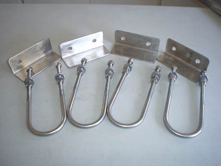
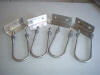 The
4 stainless u-bolts, angle plates, and hex nuts. The
4 stainless u-bolts, angle plates, and hex nuts. |
| |
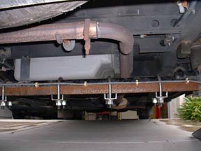
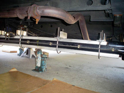
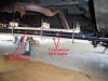 The
finished installation. Note the bottle jack in the center of the axle as
it temporarily supports the entire axle as the fasteners are torque down
to this cambered position. The
finished installation. Note the bottle jack in the center of the axle as
it temporarily supports the entire axle as the fasteners are torque down
to this cambered position. |
|
[ return to top ]
|
Additional Modifications:
|