|
[ HOME ]
|
|
Model Information
|
|
|
|
VW Service
|
|
|
|
Winnebago Service
|
|
|
|
Tours & Pictures
|
|
|
|
►
Related
Links
|
| |
On this page:
Replacement Parts
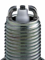
Spark Plugs:
NOTE - Because of the relative complexity of changing plugs on the VR6 engines,
don't even think about using a non-platinum or cheaper plug.
NGK's Part Number Explanation (PDF)
1995-1997EV Engine
I-5 Engine Code ACU
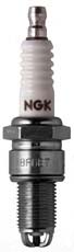
NGK # BP6ET
B =14mm thread
P = Projected Insulator type
6 = Heat Range (between 2-11)
E = Thread Reach 19mm (3/4")
T = 3 ground electrodes
|
  |
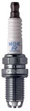
1997-2000 EV Engine
VR6 12V Engine Code AES
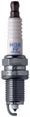
NGK # BKR5EKUP
B = 14mm thread
K = 5/8" Hex Size; Projected Tip
R = Resistor
5 = Heat Range (between 2-11)
E = Thread Reach 19mm (3/4")
K = 2 ground electrodes
U = Semi-surface discharge
P = Premium Platinum
|
  |
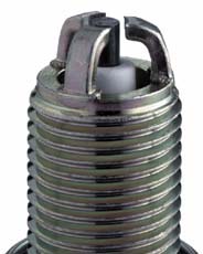
2001 - 2003 EV Engine
VR6 24V Engine Code AXK
NGK # PZFR5D11
P = Premium Platinum
Z = Extended Gap
F = 14mm thread, 19mm thread reach,
5/8" Hex
R = Resistor
5 = Heat Range (between 2-11)
D = Special Design Firing End
11 = 1.1mm Gap (.043)
|
  |
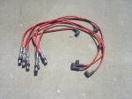
Ignition Wire Sets:
1995 - 1996 L-5 = VW # 074 998 031A
1997-2000 12V VR6 = VW # 021 998 031B or KARLYN-STI # ZVW 311 001
2001-2003 24V VR6 = No plug wires, direct connect
Use OEM quality only!! And I recommend that you do not buy any third party
wire sets. Purchase your wire sets from either a VW dealer, on any of the specialized
EuroVan or VW on-line parts houses such as "The
Bus Depot", "EuroParts-SD",
or any others that sell similar high quality OEM parts. Stay away from Pep Boys,
AutoZone, Kragen, and others that have lower-priced, lower-quality 3rd party
brands which may or may not fit correctly.
[ return to top ]
Changing Spark Plugs
(I'd welcome anyone with an I-5 engine to provide photos and
procedures.)
NOTE - This task may be too difficult for the average do-it-yourselfer.
Physically changing the plugs is not that difficult but there are several coolant
lines, vacuum hoses, and electrical connectors that must be removed in order to
gain access to the spark plugs.
The OEM spark plug installed by VW is a premium platinum tip
design which should easily last the 40,000 miles when they should be replaced.
There is no periodic maintenance required and if you go to all the effort to remove
them just to clean or check them, you might as well replace them.
TOOLS REQUIRED:
1 - ratchet socket wrench, preferably 3/8" drive
1- 12" long socket extension
1 - 6" long socket extension
1 - 5/8" spark plug socket with the rubber insert to grip a spark plug
1 - 5/8 spark plug socket without a rubber insert (more about this later)
1 - 10mm socket
1 - small tube of anti-seize thread compound
1 - piece of rubber of vinyl tubing, 3/16" ID about 18" long
1 - each of a straight tip and Phillips tip screwdriver
1 - torque wrench
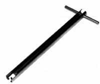
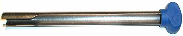
1 - spark plug boot puller tool (only needed on the AES engine)
These commercially made tools will sell for $20-$50
and they are available through Amazon.com,
EToolCart.com, and a number
of other sources such as a well stocked local automotive supply house. Try
Google.com for "VW spark plug
boot puller".
TIP - If you have a digital camera, take pictures of the engine area every
time you remove something. In that way, you will have a photographic evidence
of how to put things back together correctly. Don't trust your own memory.
MORE TIPS - Of course, make sure that the engine has completely
cooled down. And because you will be working around the radiator fans and other
electrical connectors, I suggest that you remove the negative cable from the battery
to avoid ground or shorting out anything. You should also remove the belly pan
for two reasons: one is access the wires on the radiator fans (more about that
later) and secondly, to retrieve the inevitable socket or nut that you will drop
through the engine compartment.
Procedure for 12V VR6 (1997-2000):
-
Remove the large plastic cover. It is held in place by some
plastic clips where it hooks onto the main air inlet tube. With that cover removed,
you will now see that there are a multitude of items that would need to be removed
to get to the spark plugs and wires. I will describe most of them here but you
may find it more convenient to leave one or more items in place or more convenient
to remove an additional item. Use the digital camera to record the position of
everything.
-
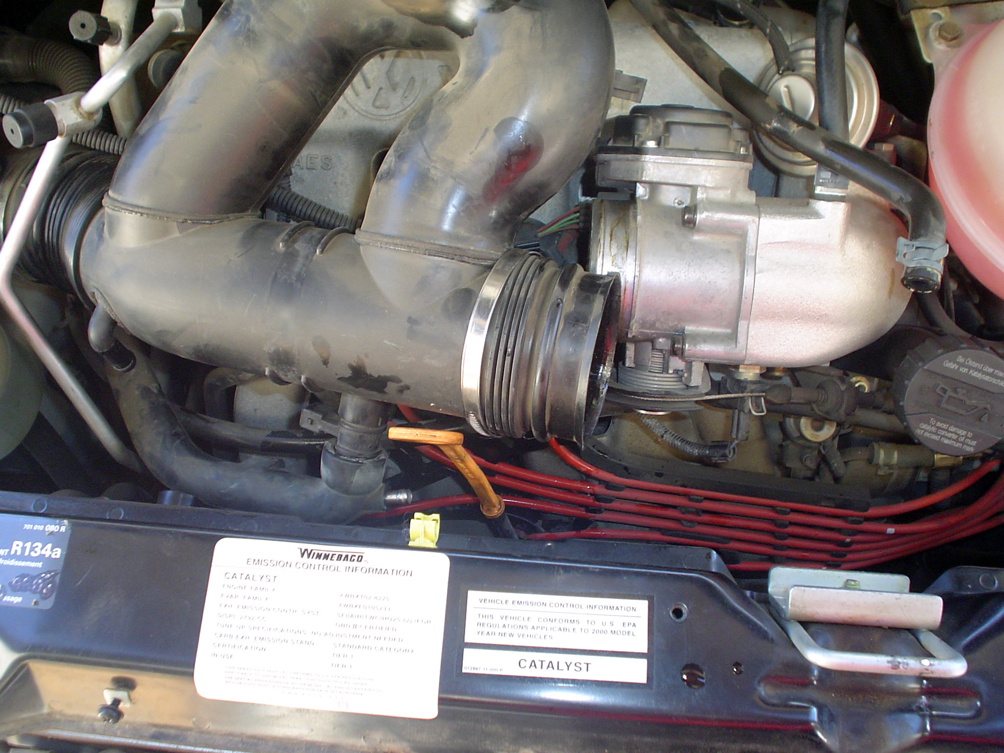
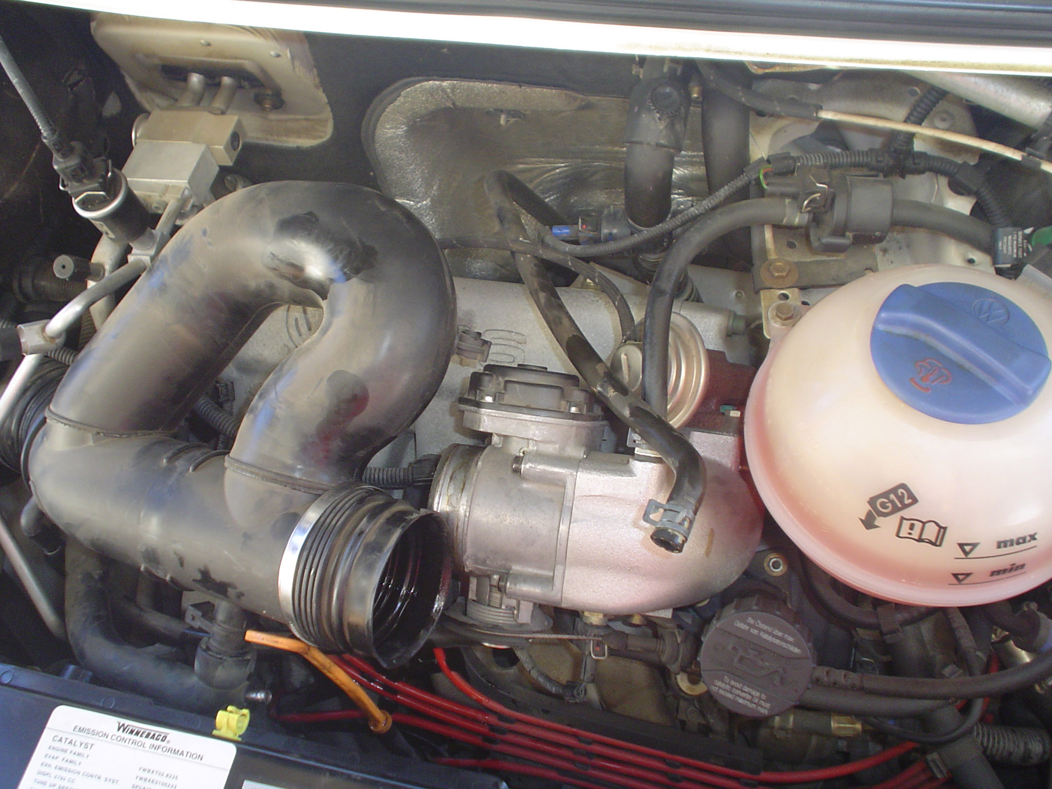
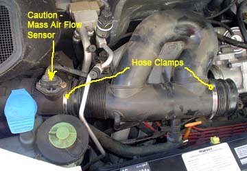
You will need to remove the large black plastic air intake
tubes that connects the air filter box to the throttle body. This large
black plastic tube looks sort of like the letter D in that it has a U-shaped tube
on one side. This large diameter air intake tube has a hose clamp at each end.
On the left side, the hose clamp connects it to the air volume meter which is
another short section of air tube. This air volume meter has the large electrical
connection at the top. On the right side of the air intake tube, the second hose
clamp connects it to the throttle body. Completely loosen both of these large
hose clamps.
-
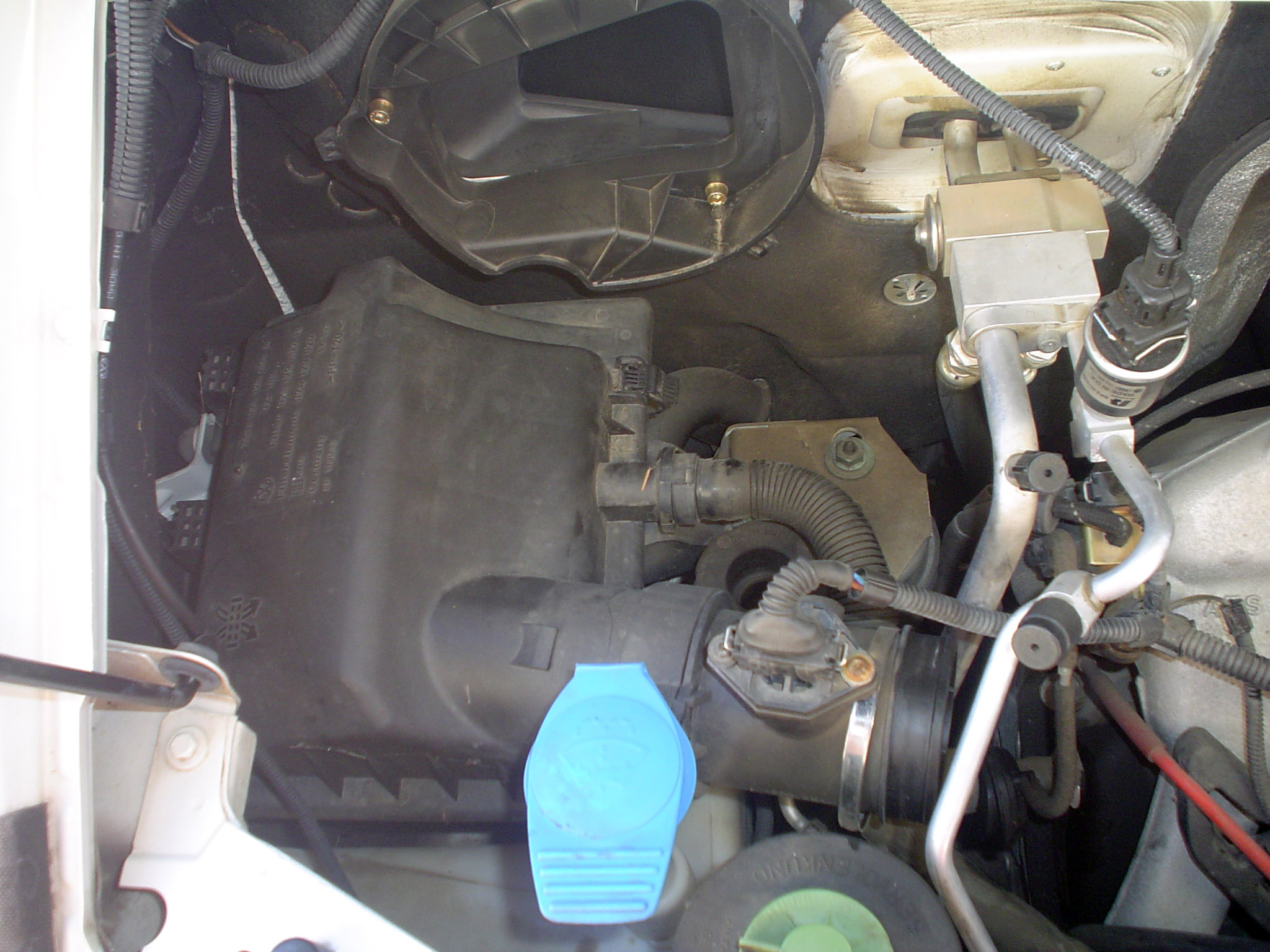
It is advantageous to disconnect the clamps holding down the
lid of the engine air filter. This will allow you a little wiggle room to remove
the large air intake tube from between the air volume meter section and the throttle
body. I actually removed not only the lid but the entire air cleaner box along
with the cabin pollen filter housing. The air volume meter section is held in
place to the air cleaner lid by three screws but I suggest that you leave it connected
as there is an o-ring that completes the seal. Besides, that little tiny sensor
hanging down in the middle of the tube costs over $300 so leave it alone!
 Caution
- there will be two other hose connections and one electrical connection to the
air intake tube that will need to be disconnected. One of the hoses connects into
the side of the larger diameter hose towards the front of the air intake tube.
This smaller diameter hose contains engine coolant and a small amount may leak
out. You may wish to cap this hose off to keep coolant from dripping out while
working. Caution
- there will be two other hose connections and one electrical connection to the
air intake tube that will need to be disconnected. One of the hoses connects into
the side of the larger diameter hose towards the front of the air intake tube.
This smaller diameter hose contains engine coolant and a small amount may leak
out. You may wish to cap this hose off to keep coolant from dripping out while
working.
TIP: This is a good place to take a digital photo to remember which hose goes
where and which electrical connection goes where. It really is practically impossible
to mix them up but a photo or a hand drawn sketch comes in very handy when its
time to put things back together.
-
With the large air intake tube, air cleaner lid with the attached
air flow sensor all being removed, you should be getting a good idea now about
finally getting access to the plugs and wires. I may have missed describing a
few items or connections but if you've followed along this far, you should be
able to figure out anything else that may hinder your access. There's probably
an wire connection or two that you may want to disconnect to get out of the way
such as the large one towards the top left side of the throttle body. The worst
part is over.
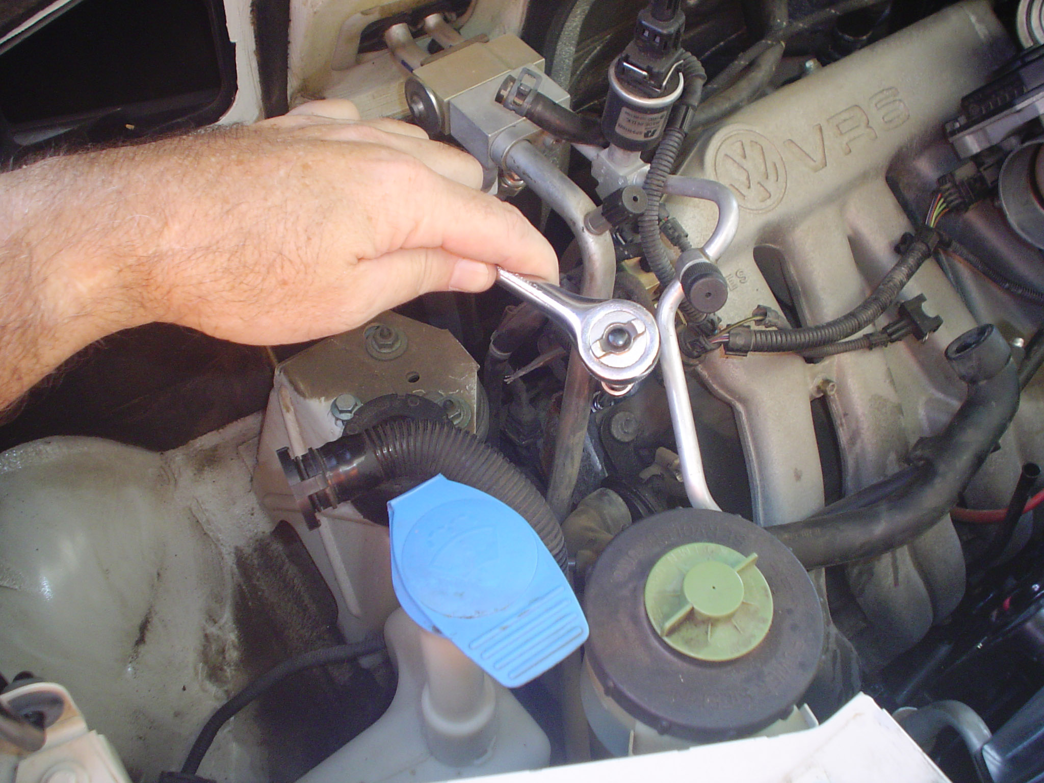
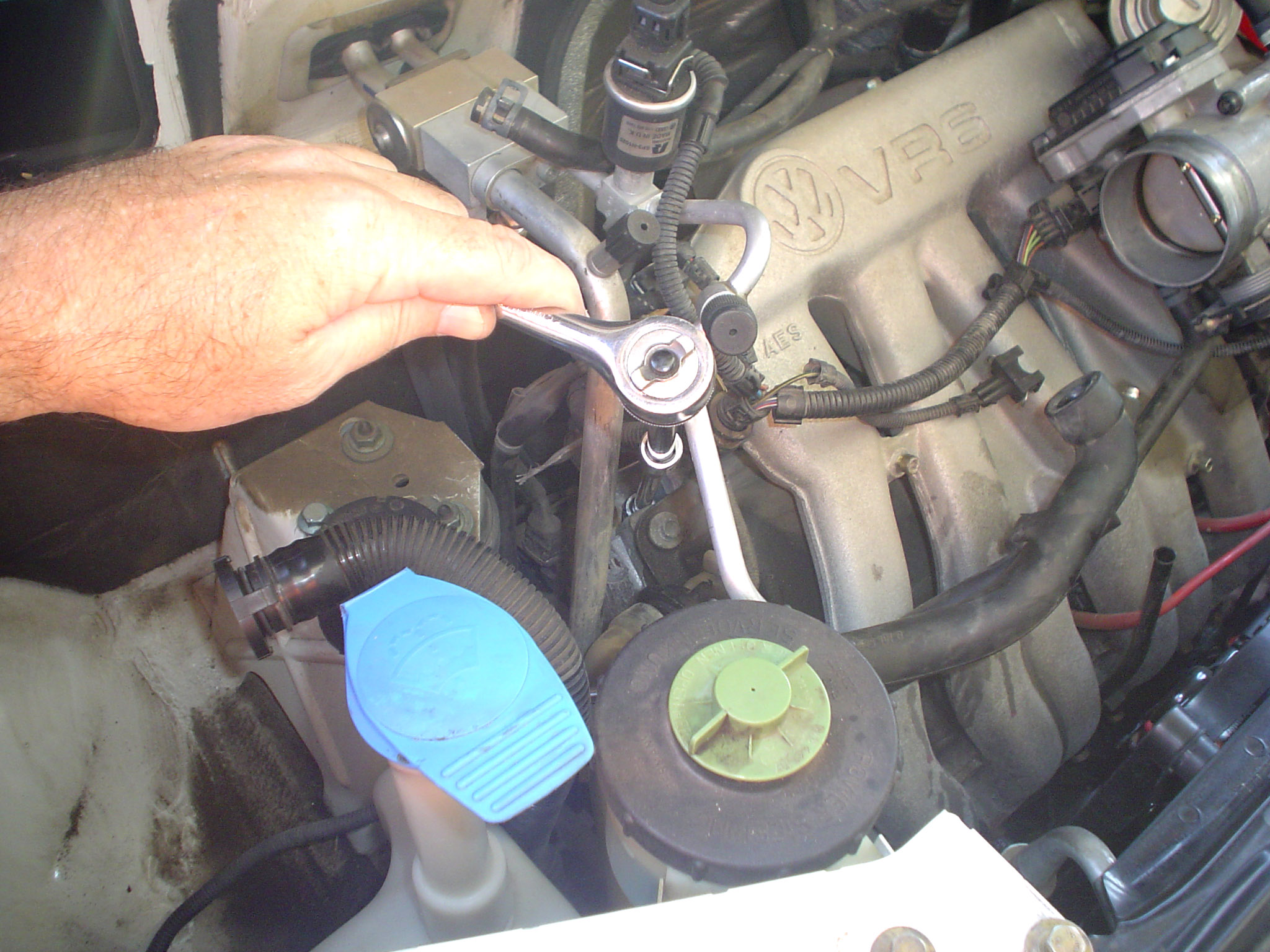
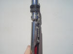
-
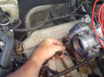
Work on only one cylinder at a time. I suggest to begin
at the upper right of the engine (the passenger side), which is cylinder #1. Insert
the boot puller tool down over the plug wire until the tool bottoms out on the
metal boot (yes it goes in a long way) and then twist about 1/8 turn clockwise
to grab the fins of the metal boot. Pull straight out on the puller tool and the
boot should slide off easily. You will use this same technique on the remaining
5 cylinders. The picture on the right side gives you a good idea of how the tool
slides down and fits onto the metal boot of the spark plug wire.
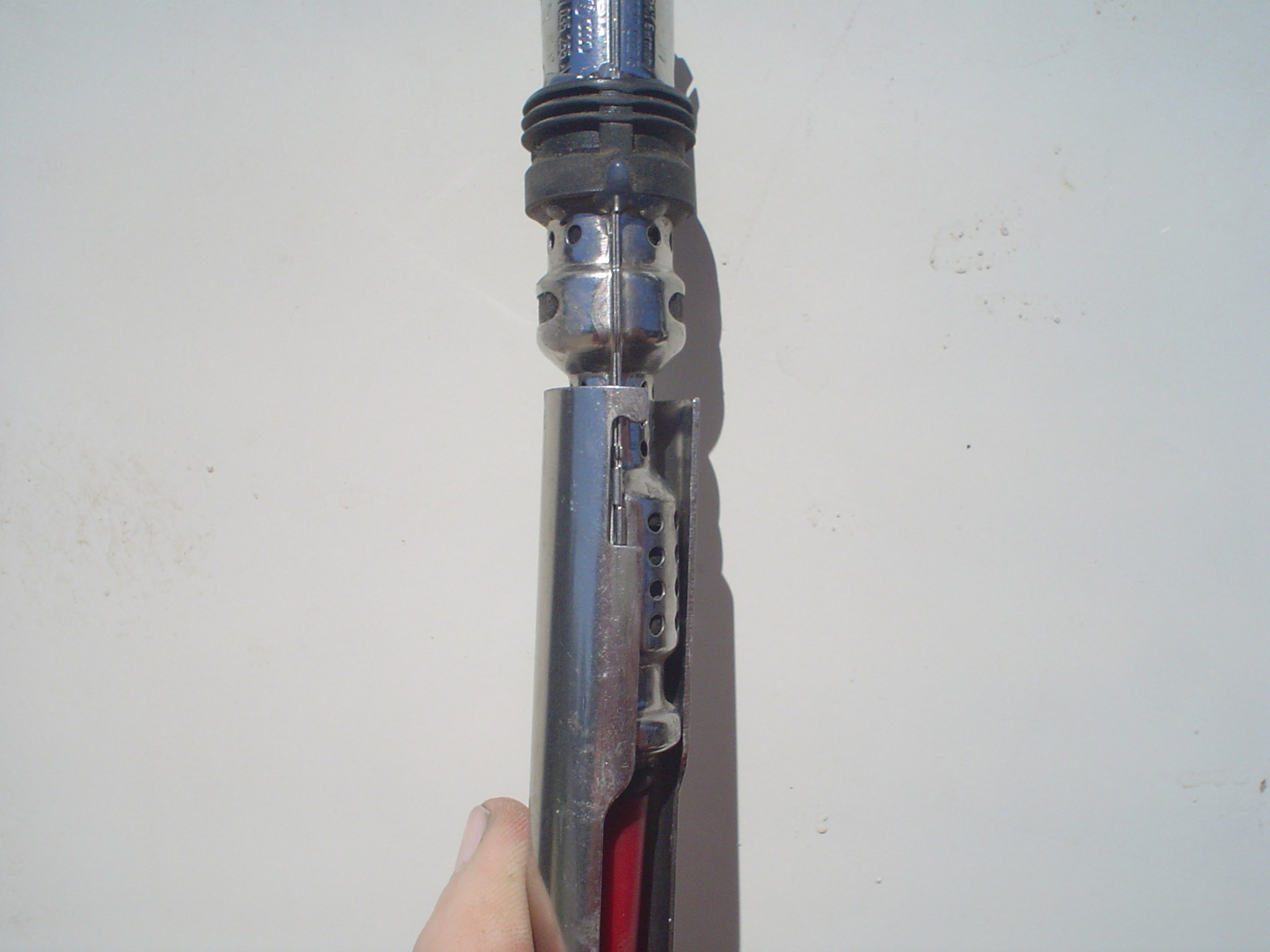
TIP - On this first cylinder, you can find that it is easy to see the exposed
plug on the side. However, this cylinder is probably the worst to get at because
of the A/C lines, vacuum lines, and electrical connections that are right in the
way. Inserting the boot puller tool such as the one made by Schley with the solid
T-handle on the end presents a
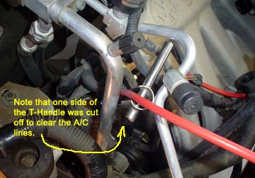 problem
because of the A/C lines that are in the way along with some vacuum lines, and
some electrical connections. You can temporarily remove the vacuum lines and electrical
wires but the A/C pipes will prevent the T-handle tool from going in all the way.
Obviously the designers of the tool never worked on a engine with air conditioning.
It would be so nice if the T-handle were the type that would slide from side to
side or would allow complete removal. My fix was to hacksaw off one side of the
t-handle. Do whatever you have to do to make your tool work for you. Other than
the tight clearance in the lower 3 cylinders, this is the only one that has a
lot of things in the way. problem
because of the A/C lines that are in the way along with some vacuum lines, and
some electrical connections. You can temporarily remove the vacuum lines and electrical
wires but the A/C pipes will prevent the T-handle tool from going in all the way.
Obviously the designers of the tool never worked on a engine with air conditioning.
It would be so nice if the T-handle were the type that would slide from side to
side or would allow complete removal. My fix was to hacksaw off one side of the
t-handle. Do whatever you have to do to make your tool work for you. Other than
the tight clearance in the lower 3 cylinders, this is the only one that has a
lot of things in the way.
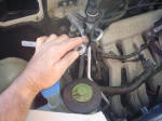
-
Once you have to wire removed from the plug, your next task
will be to remove that plug and replace it with a new one. But before you do that,
you need to make sure that any dirt or sand sitting at the bottom of the spark
plug well is removed. Otherwise, once the plug is out, that dirt and sand can
fall into the cylinder and cause damage. Some people have advocated using a can
of compressed air and a length of flexible tubing to blow the dirt away. Yes that
method works well but you can eliminate the can of compressed air and just blow
through the tubing. Just poke the tubing down the plug well to almost all the
way to the bottom. Simply place your mouth over the open end and a couple of quick
puffs of air will clean out the debris. I recommend that you keep your eyes closed
at the time because you'll be surprised just how much stuff comes out.
TIP - Trying to keep the tubing straight might be a problem. Just use a 12" long
piece of stiff wire such as an old coat hanger and tape the tubing to the wire.
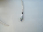
-
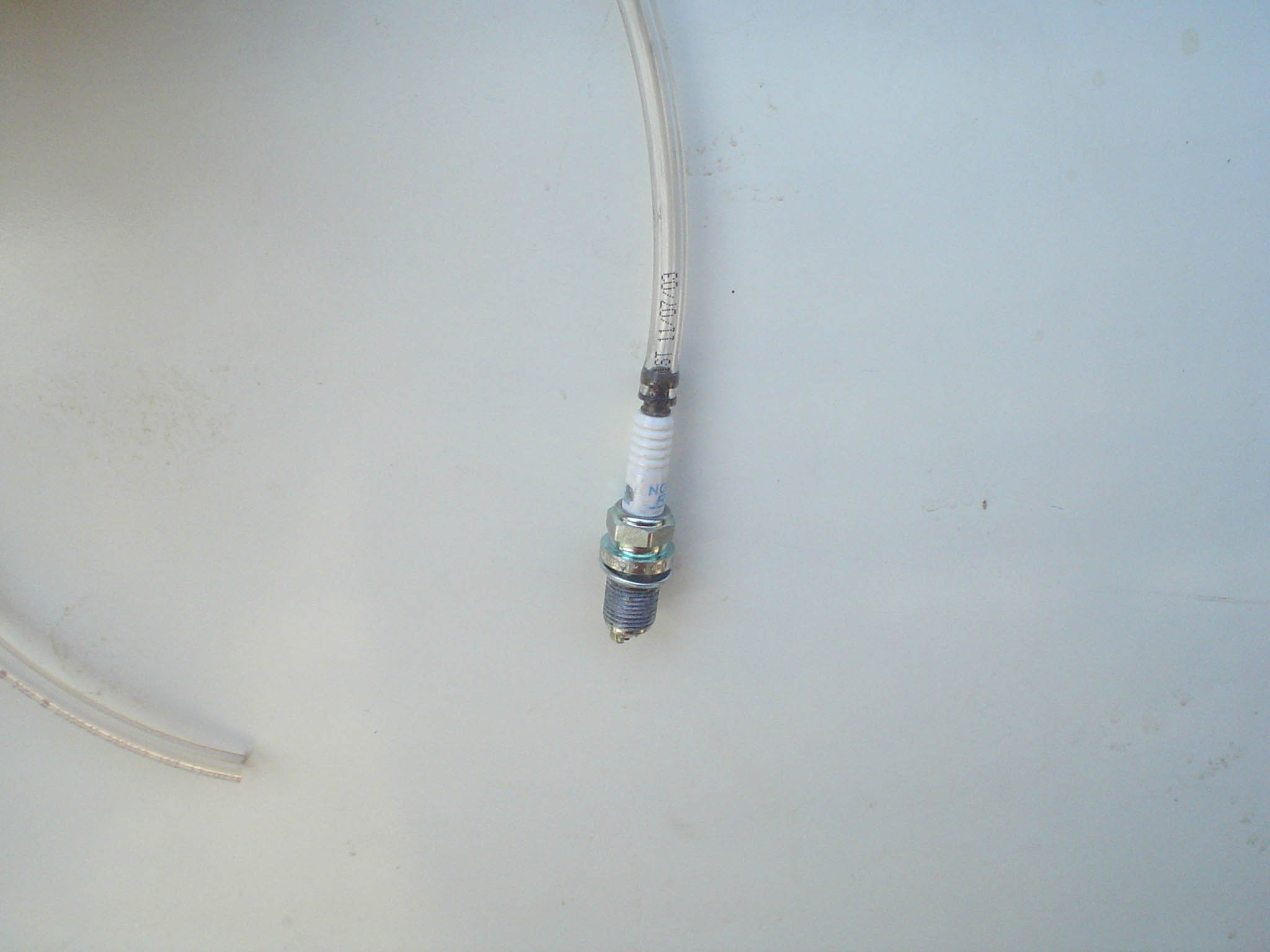
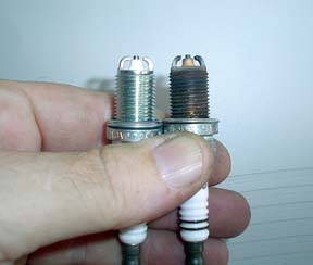
Remove the spark plug using a standard 16mm (5/8") spark plug
socket with rubber insert. On the top three cylinders (numbers 1, 3, and 5) you
will need at least a 12" extension and a 6" extension. Make sure the 12" is at
the end next to the plug. It will just clear the top of the well which is why
you need the additional 6" extension. Once the plug is removed, make sure you
don't drop anything down the spark plug well. It is well advised to immediately
install the new plug otherwise stuff a small rag into the well until you are ready
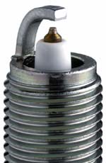
to finish the job. The picture on the right shows a new plug next to an old plug
that went 50,000 miles without a misfire.
-
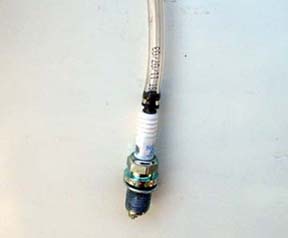
Prepare the new spark plug by applying some anti-seize lubricant
to the threads. Now comes a little tricky part and that is getting the new plug
started into the cylinder head without cross-threading it. If you use a socket
wrench, it is difficult to "feel" when the plug is starting to thread and difficult
to tell when you are cross-threading it. The solution is to use that same piece
of 3/16" ID tubing that you used to blow the dirt out of the hole only this time
you will slip the end of the tubing over the top terminal of the plug. Then slip
the plug with the tubing attached down into the plug well. With a little guidance
you'll find that it slides right into place. Now start turning the tubing until
you feel the plug threading into the hole. If it goes only a 1/2 turn and gets
very tight, then you're cross-threading.
 Back
it up and starting turning again. After a few tries, you'll feel the plug correctly
start and just make sure you can turn it at least 3 or 4 complete turns with the
tubing to make sure you have started in the thread correctly. Now just pull on
the tubing and it will slip off leaving the plug partially threaded into the hole. Back
it up and starting turning again. After a few tries, you'll feel the plug correctly
start and just make sure you can turn it at least 3 or 4 complete turns with the
tubing to make sure you have started in the thread correctly. Now just pull on
the tubing and it will slip off leaving the plug partially threaded into the hole.
Auto purists and professional mechanics will sometimes disagree with me at this
point. Technically, before a new plug is installed, the threads should be cleaned
using a spark plug thread chaser. It uses a little grease applied in a small cavity
right next to the cutting edge of the lead thread to capture and hold any dirt
that is removed. The reason for removing the dirt is to obtain a true torque reading
when the new plug is tightened to its final torque setting. If you have a spark
plug thread chaser and the know-how to use it, then go ahead. But do you really
think a dealership would do this if they were working on your car? And just how
far off could the torque reading be if the threads are a little dirty? I'll let
you be the judge.
-
With the plug started into the thread, now use your 16mm (5/8")
spark plug socket WITHOUT the rubber insert and your long extensions to tighten
up the plug. You'll feel the "crush" of the washer start which means it time to
quit with the hands and start to use a real torque wrench. The reason for using
the socket without the rubber insert is simple: once you had tightened up the
plug, when you go to pull the sockets out of the hole, the socket will come apart
where the extension attaches leaving your socket firmly attached to the spark
plug deep down in the hole. Use a torque wrench to bring the final tightening
up to 18 ft/lbs.
TIP - You may wish to invest in the more professional spark plug socket tool that
is all one piece. That eliminates the problem of the socket clinging to the plug
while the extension piece pulls out all too easily. The problem is that you would
need to find one that is about 18" long so that it can reach the top three cylinders.
Another problem is that the lower three cylinders only need about 12" of extension
so now you would need two such professional tools.
- Repeat the same process for changing the plugs on the next two cylinders at
the top (cylinders 3 and 5).
-
In order to gain access to the lower three spark plugs, you
will need to tip the radiator forward to gain that needed clearance. The top mounting
of the radiator must be loosened to allow it to tip forward. Before you do that,
you need to remove the grill section with the VW emblem that is in front of the
radiator. There are two Phillips head screws, one at each end of the grill. In
the center of the VW emblem is another bolt, probably a socket head requiring
a 5mm hex wrench. With those three fasteners removed, lift the entire grill section
out. Now you can remove the two 10mm hex head bolts along the top on each side
of the radiator. The radiator can now be pushed forward from the top to put it
in its tilted position.
CAUTION - When you do tip the radiator forward, watch the rubber coolant hoses
and the metal A/C pipes to make sure you don't pinch or dislodge any. And when
handling the electric fan assembly, be very gentle. They are expensive to replace.
You've probably heard about how the radiator tips forward to allow access to the
plugs at the front of the engine. Well, you've probably been mislead in thinking
it tipped forward a lot and gave a clear shot at everything. The truth is that
it tips forward only four inches at the top. But at the lower area where the plugs
are at, you will gain only 2 inches!! If you have a 12" long spark plug boot puller
tool, there is no way that tool will fit in the confined area around those lower
3 plugs.
TIP: After much discussion with those that thought they knew how (but had never
really done it) and a few messages from those that actually had done it, here's
the secret. With the radiator tipped forward, remove the radiator fans. They
come out as one big assembly and it takes less than 5 minutes. You now have sufficient
clearance to access the plugs. Do not even think about removing radiator hoses
and A/C lines. Do not even think about removing the lower grill panel that houses
the light. Remove the fans and all the problems go away.
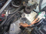
-
 To
remove the radiator fan assembly, disconnect the electrical connections before
you remove any bolts. You will probably have to crawl underneath to disconnect
these two large electrical connectors. The top portion of each connector that
has its wires running up to the fan motor is held in place on a plastic U-shaped
bracket. There is a small half-moon shaped piece of metal that is folded over
and has two crimps that hold it in place on the edges of the bracket. Use a flat
tip screwdriver to pry those clips off. They will be re-used to re-attach the
connectors when finished. Once that metal clip is removed the connector will be
hanging free and you can easy pull the two halves apart. You will note that each
connector has only a brown wire and a red wire. Only a color-blind person could
put them together backwards. There is also a plastic cover about 10" long and
looks sort of like an open mesh flat cover. It does nothing other than cover over
the wires where they come out of the fan and are directed towards the center and
then down to the connections at the bottom. This plastic cover will need to be
opened up so that the wires are free to be moved out with the fans. There are
some small clips and tabs that hold it in place. To
remove the radiator fan assembly, disconnect the electrical connections before
you remove any bolts. You will probably have to crawl underneath to disconnect
these two large electrical connectors. The top portion of each connector that
has its wires running up to the fan motor is held in place on a plastic U-shaped
bracket. There is a small half-moon shaped piece of metal that is folded over
and has two crimps that hold it in place on the edges of the bracket. Use a flat
tip screwdriver to pry those clips off. They will be re-used to re-attach the
connectors when finished. Once that metal clip is removed the connector will be
hanging free and you can easy pull the two halves apart. You will note that each
connector has only a brown wire and a red wire. Only a color-blind person could
put them together backwards. There is also a plastic cover about 10" long and
looks sort of like an open mesh flat cover. It does nothing other than cover over
the wires where they come out of the fan and are directed towards the center and
then down to the connections at the bottom. This plastic cover will need to be
opened up so that the wires are free to be moved out with the fans. There are
some small clips and tabs that hold it in place.
 CAUTION
- You will find that this 10" long plastic cover has plastic clips that are very
fragile. If you pry up on one to allow it to slide over a tab so that you can
remove it, you may find that the entire plastic clip will break off. Don't panic.
This cover serves no other function than to keep the wires from flopping around
in the breeze. Even if you break all the plastic clips (not likely), just use
some wire zip ties to hold the cover back in place. Nobody will ever know and
I won't tell. CAUTION
- You will find that this 10" long plastic cover has plastic clips that are very
fragile. If you pry up on one to allow it to slide over a tab so that you can
remove it, you may find that the entire plastic clip will break off. Don't panic.
This cover serves no other function than to keep the wires from flopping around
in the breeze. Even if you break all the plastic clips (not likely), just use
some wire zip ties to hold the cover back in place. Nobody will ever know and
I won't tell.
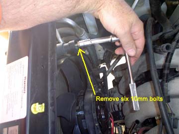
With the electrical connections free, remove the six 10mm bolts that hold the
radiator fan assembly in place. As you remove the last bolt, you should be holding
onto the fan assembly. Once free, just lift straight up and out.
CAUTION - Handle the fan assembly with extreme care. Set it in a safe place while
you are finishing the work. Do not pile any other objects on the fans. They are
very expensive so treat them with care.
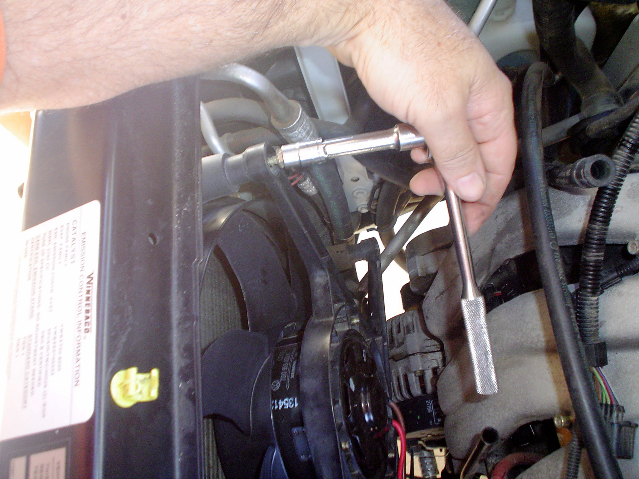
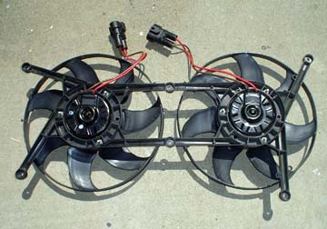
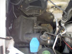
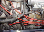
-
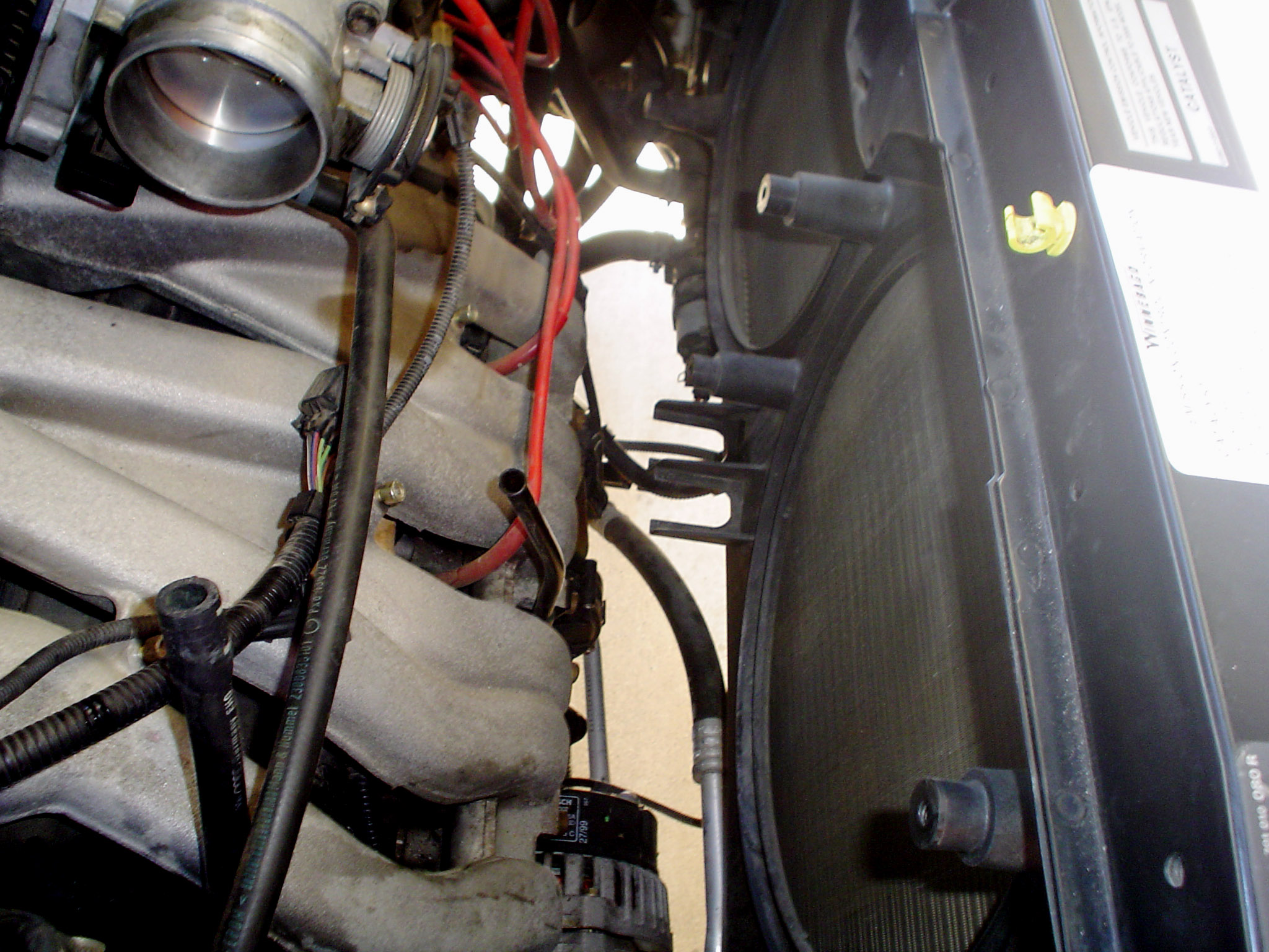
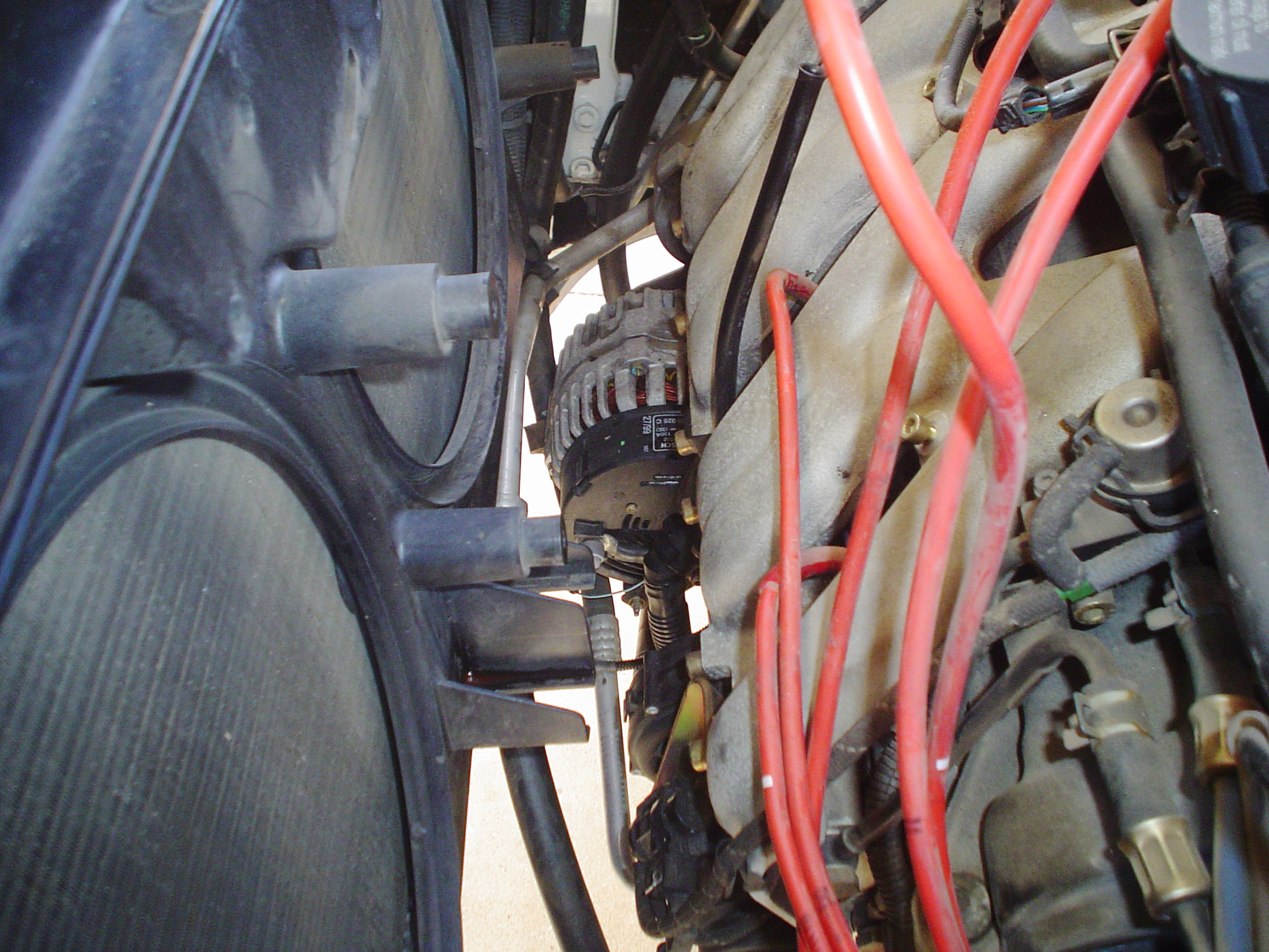
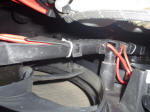
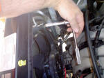
Once the radiator fans have been removed, you will
find plenty of room to use the 12" long boot puller tool and your 12" extension
for the spark plug socket. Use the same procedure previously followed on the upper
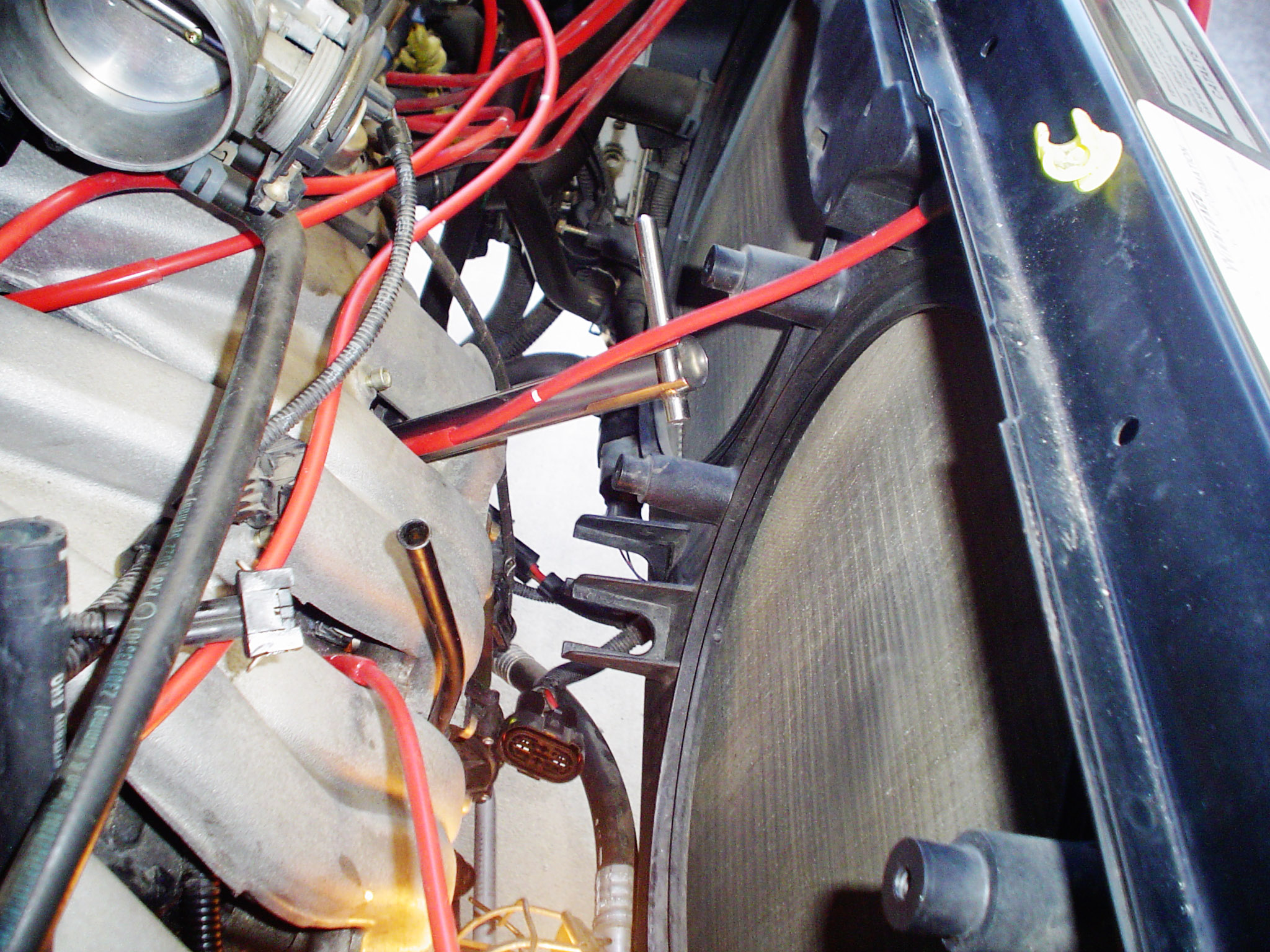
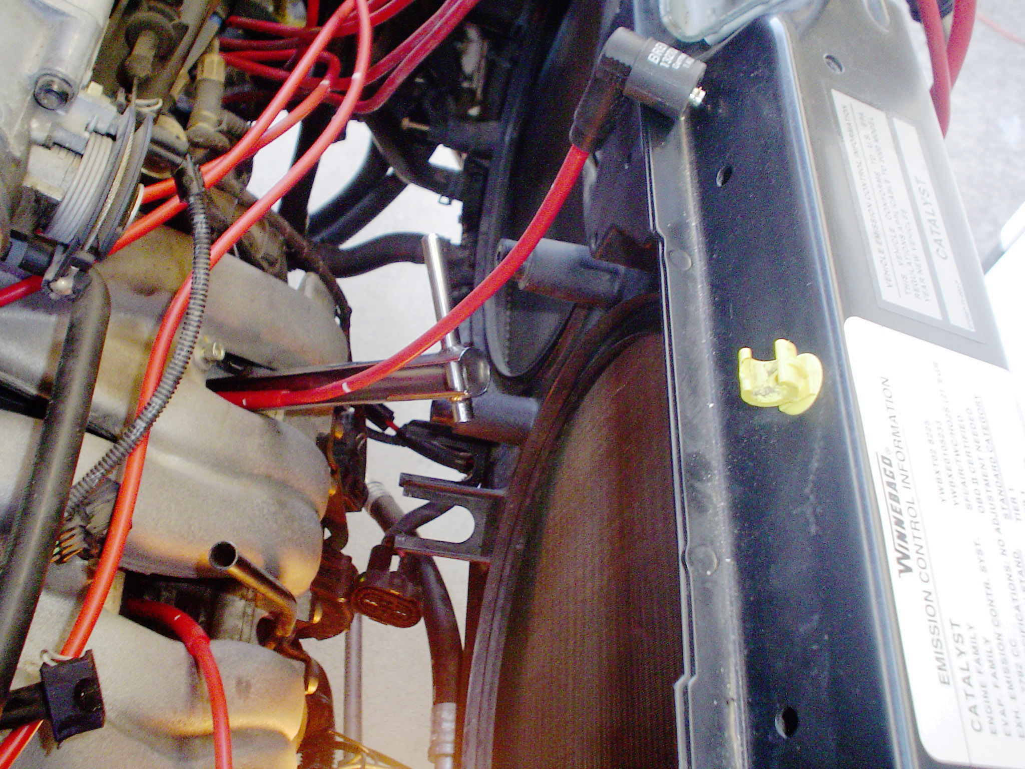
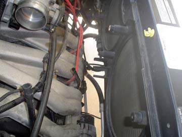
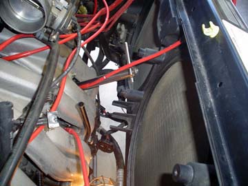
three cylinders on these three lower cylinders. View the pictures below to see
the access clearance gained by removing the fans and how easily the long boot
removal tool can fit.
 |
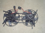
 |
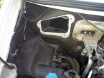
| Radiator fans removed. Note the 2 U-shaped plastic brackets at the bottom
center of the radiator. These hold the electrical connectors in place. |
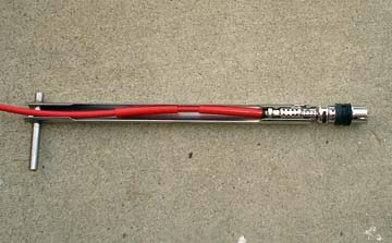
12" long boot removal tool inserted in cyl #6 and still has plenty of
clearance. This would not have been possible with the fans in place. |
-
After replacing the three lower spark plugs and reattaching
the spark plug wires, you should immediately replace the radiator fan assembly
before something happens to it, i.e. somebody walks on it, etc. Installation is
just the reverse of removal. Hold the assembly in place with one hand and start
one of the 10mm bolts in place. You will find that the plastic mount of the fan
assembly snaps over the plastic mount of its frame. Do not tighten the bolts until
all are in place. Once all the bolts have been tightened down, crawl back underneath
and reattach the two electrical connectors (brown to brown and red to red). Slide
each connector in place on the plastic U-shaped bracket. Push the metal clip in
place. You may need a small hammer to tap it all the way to the correct position.
TIP- If the metal clip slides onto the bracket too easily, it will fall off from
road vibration. You may need to place the clip on a flat hard surface and hit
it lightly with a hammer to SLIGHTLY close up the edge so that it gets more of
a bite on the bracket. Hit once with a hammer and then try it. Do not hit it several
times only to find out it is now too tight.
-
Move the top of the radiator back into place and replace the
four 10mm hex head bolts. Replace the front grill assembly. Before you replace
the large black air intake tube, check for any other electrical connector, vacuum
hose or coolant hose that you may have temporarily moved to gain access. Reattach
the battery cable if you removed it. Once you are sure that you haven't missed
anything, replace the black air intake tube along with all of its related hoses
and connections.
-
With all tools accounted for and rags and other items removed
from the engine area, start the engine. Let it idle for a few minutes. Give it
a little gas. You should not see the Check Engine Light come on which would probably
indicate a misfire on one or more of the cylinders if for some reason you failed
to completely seat the spark plug wire and boot assembly. Assuming that everything
is OK, congratulate yourself on completing this job successfully.
[ return to top ]
Procedure for 24V VR6 (2001-2003)
This procedure will be rewritten. The one that was here was for the 12 valve engine (AES), not the 24 valve (AXK)
[ return to top ]
Spark Plug Gap
These measurements are all based on using the original
specified spark plug. Most manufacturers will indicate that their plugs are "pre-gapped"
but its a good idea to check before installing.
1995-1996 I-5 Engine ACU = 0.8mm (0.032 inches)
1997-2000 VR6 140hp AES = 0.7mm (0.028 inches)*
2001-2003 VR6 201hp AXK = 1.1mm (0.044 inches)
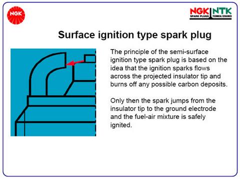
* These plugs are a
"semi-surface ignition" spark plug and the method of measuring the gap is different
than a convention plug. The gap on these plugs refers to the distance between
the projected insulator tip and the ground electrode.
These are preset from
the factory. No need to gap. The gap isn't between the center and ground electrodes.
This spark plug gap is the air gap between the backside of the ground electrode
and the insulator.
JM
Technical Support Specialist
***********@ngksparkplugs.com
Also note that these plugs have two ground electrodes
but only one spark will be generated determined by the path with the least resistance.
[ return to top ]
Changing Ignition Wires
 In
my opinion, its kind of a mistake to not change the spark plug wires at the same
time as the spark plugs. This is done only every 40,000 miles or longer and you
have completed most of the work just getting to the plugs. Changing the ignition
wires at that point is very little additional labor. Just make sure you buy a
high quality brand such as the OEM product from a VW dealership or reputable online
source. In
my opinion, its kind of a mistake to not change the spark plug wires at the same
time as the spark plugs. This is done only every 40,000 miles or longer and you
have completed most of the work just getting to the plugs. Changing the ignition
wires at that point is very little additional labor. Just make sure you buy a
high quality brand such as the OEM product from a VW dealership or reputable online
source.
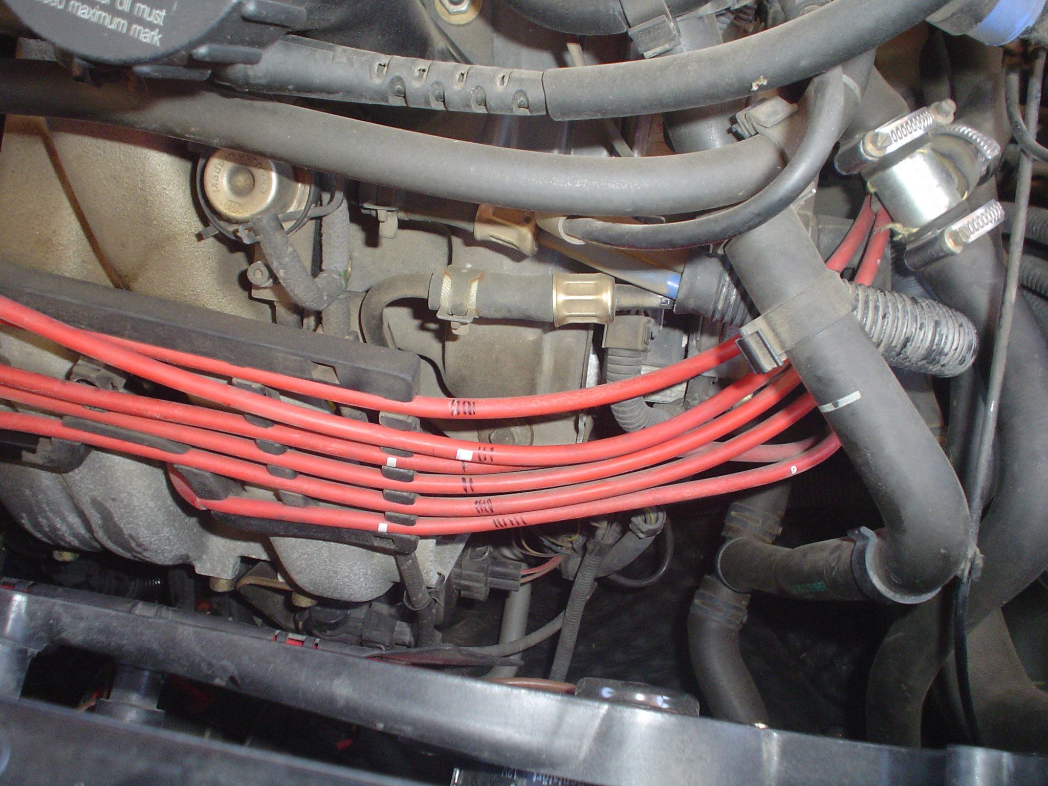
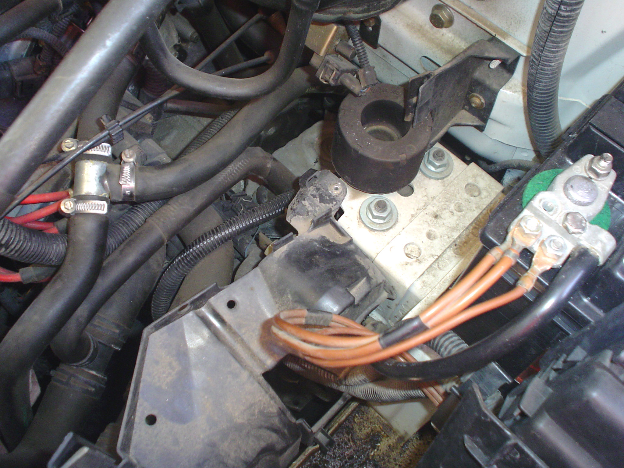
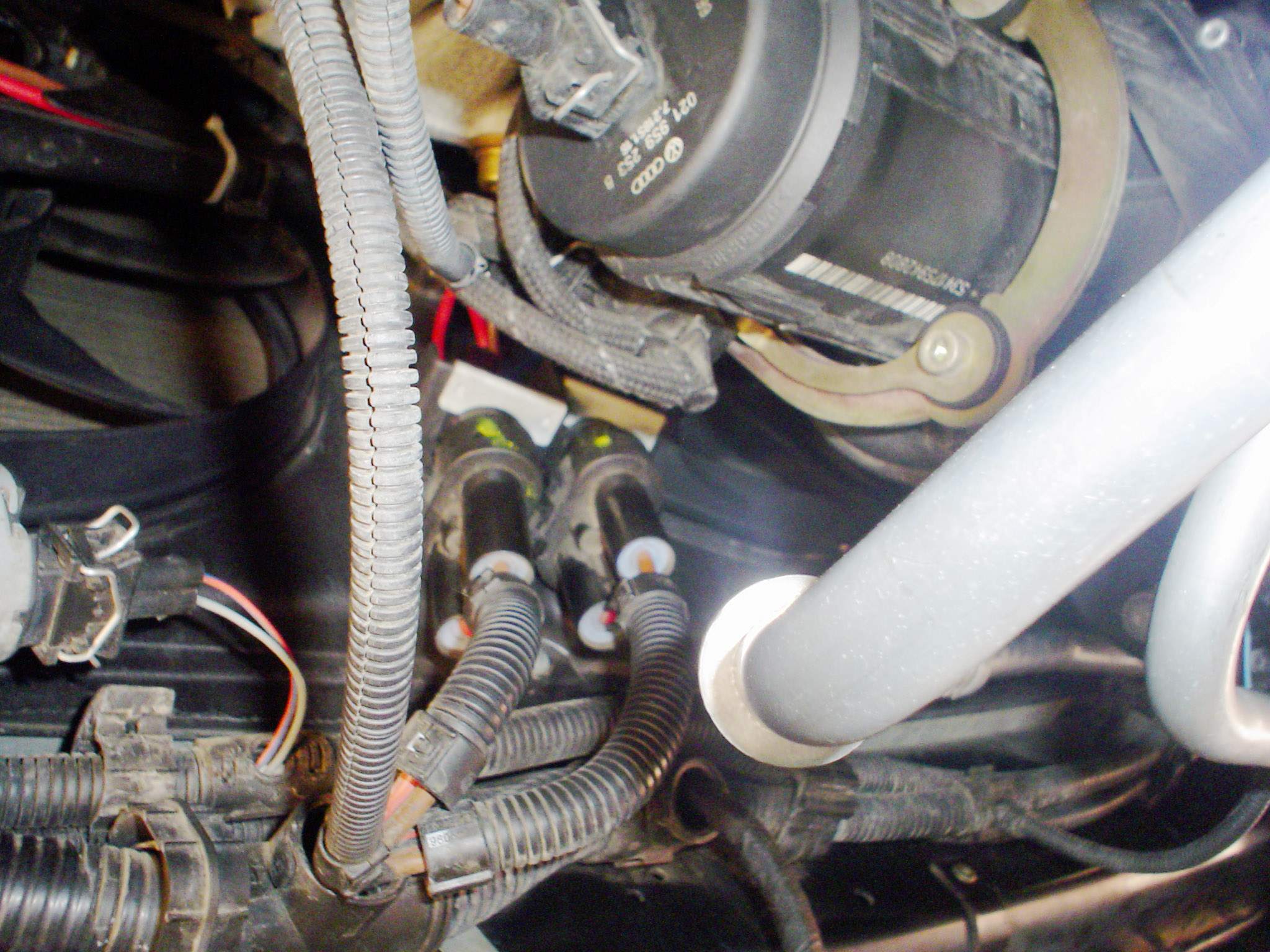
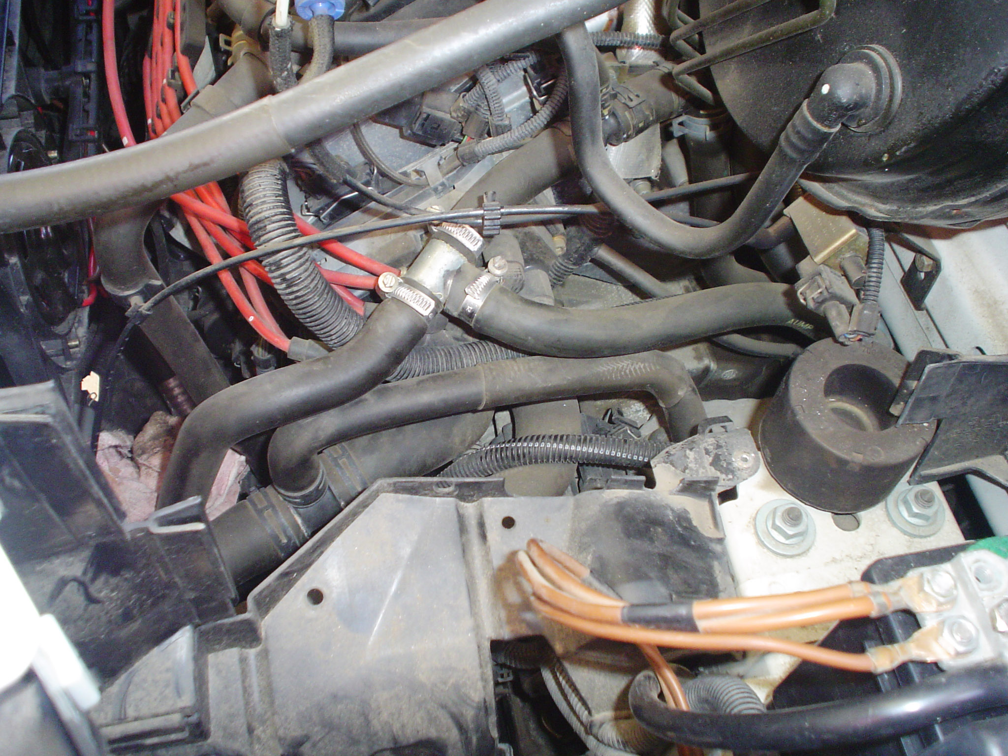
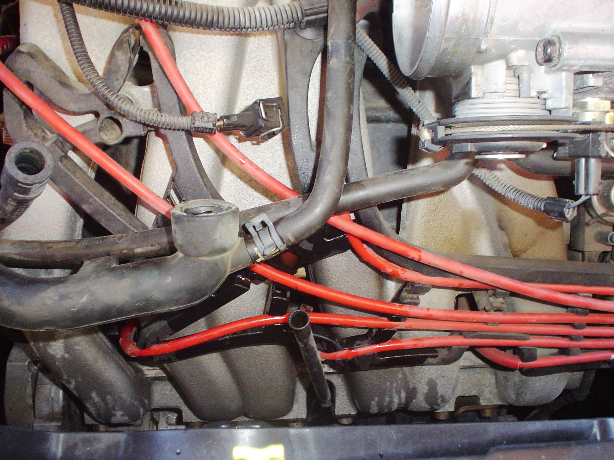
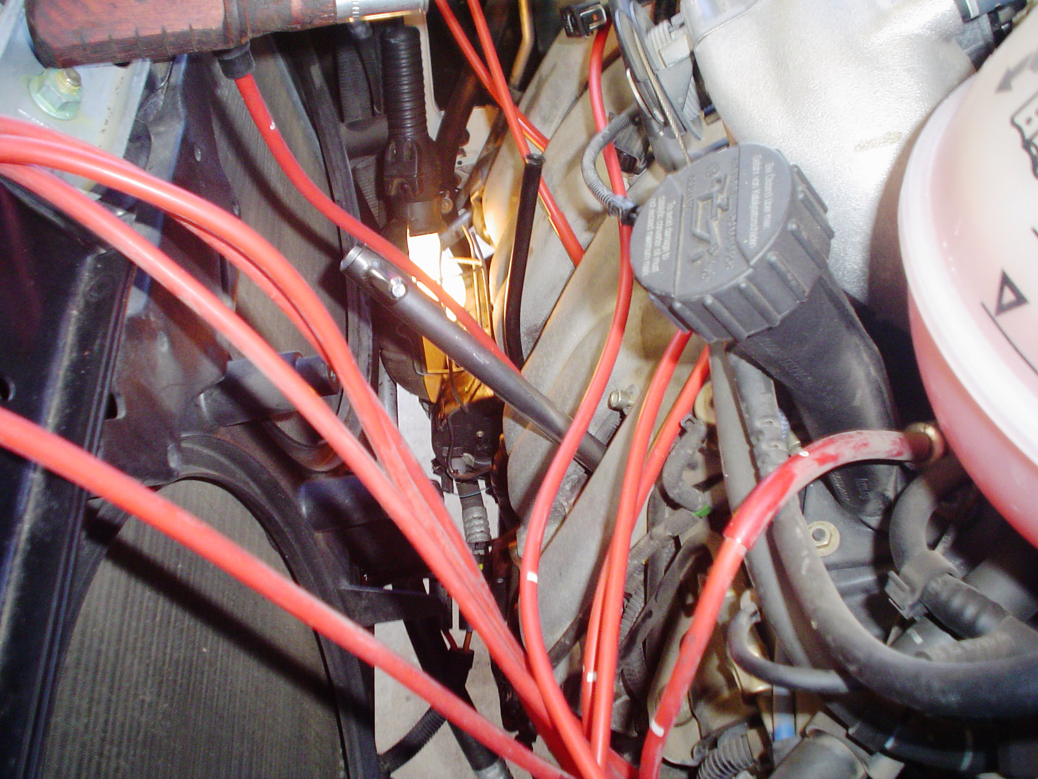
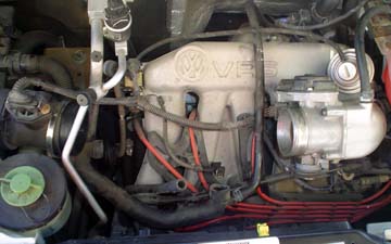
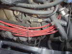
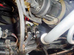
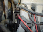
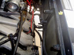
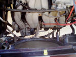
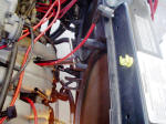
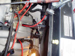
 There
is one minor problem in changing the wires on the I-5 and 12V version of the VR-6.
It is somewhat difficult to see the actual terminals on the ignition coil and
most of the pulling the old ones off and putting the new ones on will be done
relying mostly on "feel" instead of "sight". There is one solution to this lack
of sight problem and that involves removing the plastic battery box parts (see
picture at right). It looks very easy as all the parts just snap into one another
but you'll find the main side section is pop-riveted in place at two spots. I
drilled out the pop-rivets so it wasn't really that much of a hassle but I don't
think I gained any time by doing so. There
is one minor problem in changing the wires on the I-5 and 12V version of the VR-6.
It is somewhat difficult to see the actual terminals on the ignition coil and
most of the pulling the old ones off and putting the new ones on will be done
relying mostly on "feel" instead of "sight". There is one solution to this lack
of sight problem and that involves removing the plastic battery box parts (see
picture at right). It looks very easy as all the parts just snap into one another
but you'll find the main side section is pop-riveted in place at two spots. I
drilled out the pop-rivets so it wasn't really that much of a hassle but I don't
think I gained any time by doing so.
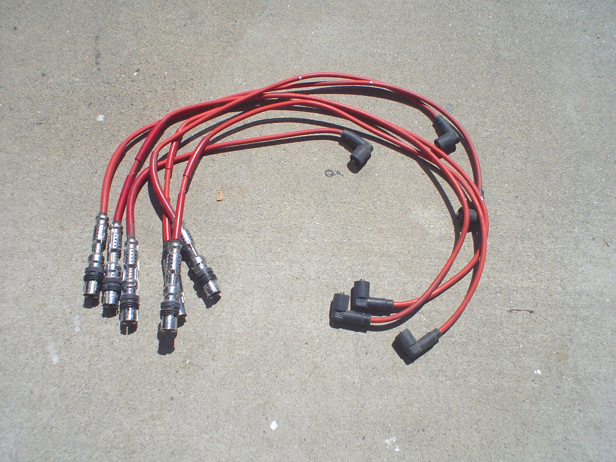
Unless you are totally familiar with the engine
firing order and the correct numbering of the terminals, I strongly suggest that
you replace only one wire at a time. Almost all of the OEM quality wires will
have the cylinder number marked on the wire. Simply remove one old wire, and replace
with a new wire of the same number. You probably should hold the old one and the
new one together just to confirm that they are the same length.
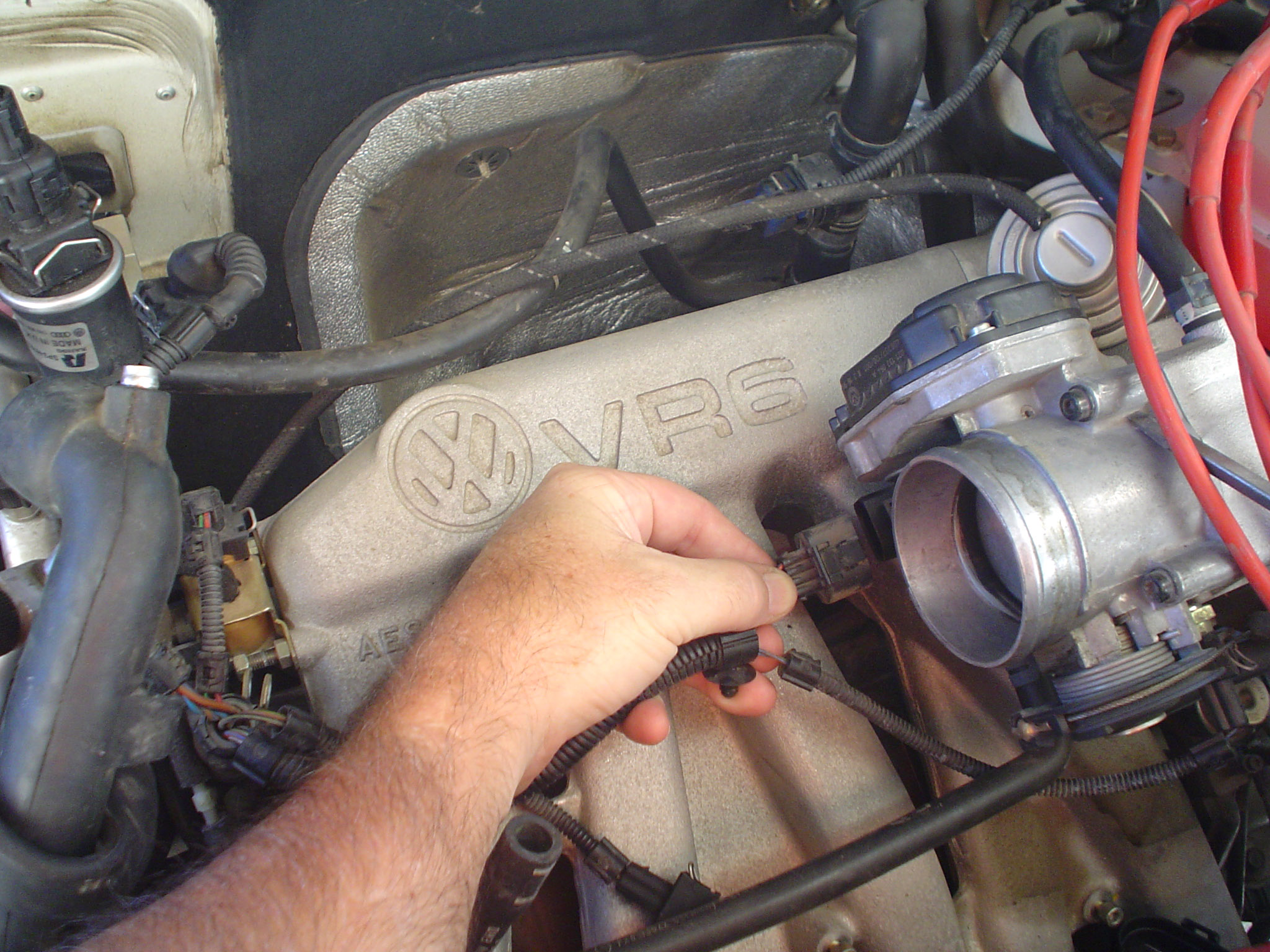
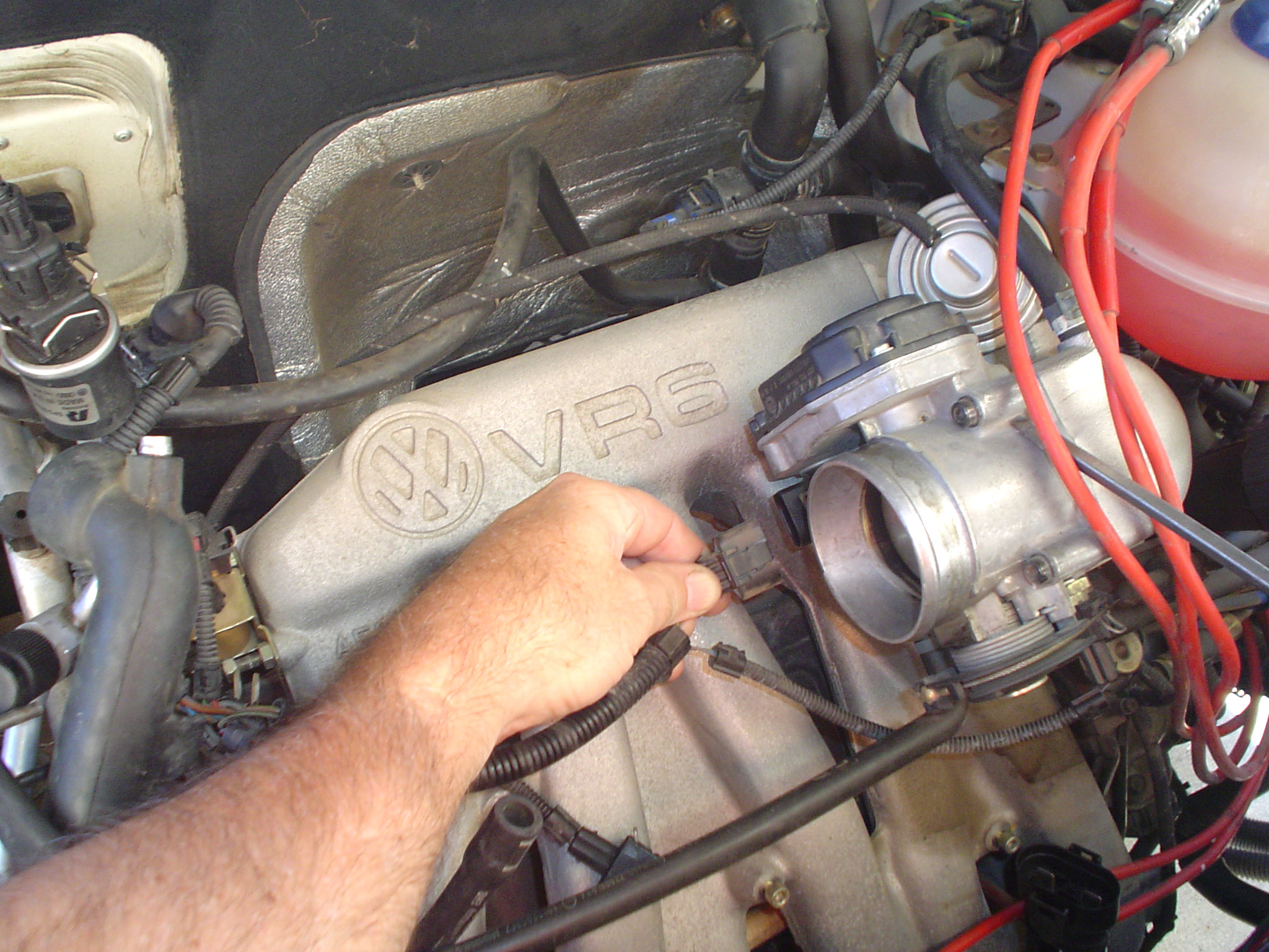
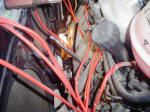
 The
hardest problem is getting the old terminals connectors off because the nipple
caps tend to stick in place. Use a flat tipped screwdriver to help push the edge
of the nipple cap off just slightly and you'll find everything removes much easier. The
hardest problem is getting the old terminals connectors off because the nipple
caps tend to stick in place. Use a flat tipped screwdriver to help push the edge
of the nipple cap off just slightly and you'll find everything removes much easier.
[ return to top ]
Additional Photos
Note- All of the following photos depict certain actions while
changing the spark plugs and ignition wires on a 2000 Rialta/EuroVan V6. Some
are taken only to provide documentation of hose and wire hookups so that re-assembly
can be done without guesswork. All photos are in high resolution which means your
web browser may automatically resize the image so that it fits your screen resolution.
If it does resize the photo, you can click the resize gadget in the lower right
of the photo to instruct your browser to view it in full resolution.


[ return to top ]
|