Microwave Convection Oven

 [ HOME ]

Model Information

Miscellaneous
Accessories
Floor Plans & Specs
How To Buy Or Sell A Rialta
Known Problem Areas
Modifications, VW & Coach
New to RVing? Info here
Pros & Cons of a Rialta
Vehicle Checklist
VIN Information
Winter RV Storage

VW Service

Air Conditioner
Brakes
Door & Locks
Engine Battery
Engine Repair Information
Filters
Fuses: Dash & Engine
Mechanics & Dealers List
NHTSA Recall Notices
Oil Change
Parts Diagrams
Radiator & Coolant
Serpentine Belt
Service & Tech Bulletins
Spark Plugs & Ignition Wires
Transmission Service

Winnebago Service

Appliance Recalls
Bulbs
Caulking and Sealants
Coach Batteries
Electrical Breakers & Fuses
Furnace & Thermostat
Generator
Microwave, Range & Oven
NHTSA Recall Notices
Paint Codes
Parts Catalog
Plumbing Diagrams
Refrigerator
Service Bulletins
Shocks and Air Springs
Shower
Supplier Links
Tires & Wheels
Toilet
Water Heater
Water Pumps & Filters
Winnebago Corporate Info
Wiring Diagrams

Tours & Pictures

Public RV Sanitary Dumps
Strange & Unusual Places
Winnebago Factory Tour

   ► Related Links


This modification was originally submitted on the Tech Rally group on Yahoo by Les Fields in September 2004.  (Some comments and clarifications were added; these comments are all italicized.) PDF (73KB)

Install a Sharp R-820 Microwave/Convection Oven (FD)

Upgrade the standard microwave to a microwave / convection oven.

NOTE - There appears to be several models of the Sharp R820 microwave and I'm not sure which specific model this person used but all seem to have the same dimensions so it wouldn't make much difference.

Also note the the depth dimension of the current model of the Sharp R820 is 19-1/4" whereas the depth of the original Samsung is only 14-5/8".  This difference is 4-5/8" which I can only assume means the newer Sharp will mount farther back.  The finished picture seems to show that it doesn't stick out any further than before.  The instructions are silent about this.

Installed on 2000 FD

APPROX. MODIFICATION TIME: 2 hours

PARTS LIST:

All prices are pre tax.

Sharp R-820 Microwave/Convection Oven ≈ $250
   
1-1/2" W X 3/4" H steel tubing 16 inches long $5
1/8" thick X 1-1/4" wide flat steel 36 inches long $5
*Various sheet metal screws $2
POP Rivets 36 ea. 1/8" and 5 ea. 3/16" $2
Metal flashing 6" to 12" wide X short as possible.  Comes in a roll available at local hardware stores $5
Flat black spray paint $2
APPROX. TOTAL COST OF PARTS  $21

TOOLS:

Drill, Electric Screwdriver, Saber Saw w/ metal cutting blade, Metal Punch, Pop Rivet Gun, Tin Snips, Square, 3/16" and 1/8" drill bits, Vice Grips or C-clamps

INSTRUCTIONS:
  1. Remove the microwave oven but not the metal frame (frame) at this time.

  2. The frame needs to be moved to the front of the edge of the wood sides as far as practical.

  3. I measured mine from the front of the frame to the back edge of the plastic molding.  In my case it was 1-9/16".  This measurement is critical and will be used many times in this project.  I will refer to this measurement as "XXX."

  4. Remove the frame saving all screws.

  5. Using the Saber saw cut the 1-1/2 X 3/4" [steed tubing] into two 8" lengths.  Note: 3/4" square tubing may be used, just double up.

  6. Measure the depth of the frame and divide by two and cut the bottom support railings at the halfway point.  The two halves of the frame will be joined back together using the steel tubing.

  7. Slide the steel tubing in one side of the support railing about 2 inches and clamp.

  8. Slide the other end of the tubing in the other side and adjust the distance between the two halves of the frame to the "XXX" measurement and clamp.

  9. Do the same to the other side.

  10. Double-check the "XXX" measurement.

  11. Then, using 1/8" drill and pop rivets attach two sides together.  I used 8 rivets on each end. (16 per side).

  12. Repeat on the other side.

  13. Draw a line down the center of the 1/8 X 1-1/4 X 36 inch flat bar.

  14. Cut 5 pieces three inches long.

  15. Starting at one end, use the punch to mark a point 3/8" from the end on the centerline.

  1. Measure from that point "XXX" and mark another point.

  2. Repeat on all 5 pieces.

  3. Drill a 3/16" hole at both places on all 5 pieces.  These pieces are used to extend the top mounting holes of the frame by "XXX" so that the original mounting holes in the ceiling can be used.

  4. Using 3/16" pop rivets, rivet the 3/8" ends of the five pieces by placing the rivets through the top of the frame then place the pieces on the bottom and "pop."  The use of rivets allows some movement of the extensions from side to side for ease of installation.

  5. Mount the metal frame using the original hardware.  Leave the top screws a little loose.

  6. Using a pair of scissors or tin snips cut pieces of aluminum flashing to fit between the hole extensions to cover the ceiling fabric.  When the screws are tightened the hole extensions will hold the aluminum flashing in place.

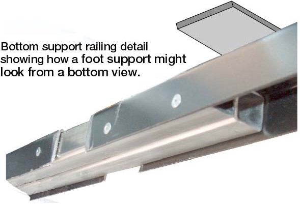
  7. Cut 4 pieces of the 1-1/4" flat bar 3 inches long.  These will become the foot supports.

  8. Temporarily set the R-820 in the frame.  The width of the support rails is too close together for proper support.  Mark on the railings the center of where the feet would be if the width were correct.

  9. Remove the R-820.

  10. Set one of the flat bar pieces on the top of the support rail centered on one of the marks made in the last step.

  11. Align one of the 1-1/4" sides flush with the inside edge of the support rail.

  12. Clamp, drill and pop the flat bar to the support rail.

  13. Repeat for the other three foot supports.

  14. I used two 1/8 rivets per support.

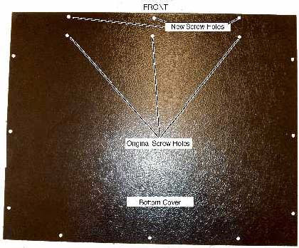
  15. Re-attach the wood panels to both sides.  The panels will end up being in the same physical location as when we started but the frame will now be nearly flush with the front edges.  New screw holes are required.

  16. Temporarily set the R-820 in the frame.

  17. Next is the top and bottom trim/vent installation.  I used the trim that was used on the old microwave.  The top piece fit beautifully.  Set it in place and mark the front edge on the top of the R-820.

  18. I used the screw from the old microwave to attach the top trim.  Be careful when drilling holes in the R-820.  Damage could result if you drill too far.  Check the depth of the hole with a probe to make sure the screws are not to long.

  19. The bottom trim piece requires a bit more work.  First, for cosmetic reasons, mask and paint a flat black 6-inch strip on the bottom front of the R-820.

  1. As before, set the bottom trim piece in place and mark the front edge.

  2. Using a combination of trimming and flat washers as spacers, fashion to fit and attach as above.

  3. The bottom cover was a surprise since it required very little to make it fit.  Using a square measure from the center of the front mounting holes forward "XXX" and drill 3/16" holes.

  4. Replace the bottom using the original screws.


Additional Modifications:

[ Arm Rest Removal ] [ Automatic Transfer Switch ] [ Awning ] [ Bathroom Shelf & Basin ] [ Battery Disconnect ]
[ Belly-Pan Cutout ] [ Bicycle Rack ] [ Cabinet Storage ] [ CB Radios ] [ Center Console ]
[ Closet Shelf ] [ Coach Door Seals ] [ Coach Entry Floor ] [ Computer Table ] [ Convex Door Mirror ]
[ Curtain Track ] [ Door Catch ] [ Daylight Running Lights ] [ DVD Conversion ] [ Entertainment Center ]
[ Entry Handrail ] [ Exterior Power Inlet ] [ Exterior Shower Drain ] [ Fuel Pump Jumpers ] [ Furnace Vent ]
[ Galley Faucet ] [ Generator Fuel Cutoff ] [ Granite Countertop ] [ Headboard ] [ Jack Handle Storage ]
[ LCD TV Conversion ] [ LED Bulbs ] [ Magnum Shooters ] [ Map Box ] [ Microwave Convection Oven ]
[ Propane Detector ] [ QD-H Conversion ] [ Rear Axle Stiffener ] [ Rear Couch Foam Roll ] [ Heat Control Label ]
[ Rear Seat Kick Panels ] [ Refrigerator DC Mode ] [ Refrigerator Conversion ] [ Roof Air 13,500 ] [ Roof Rack ]
[ Satellite Dish ] [ Sewer Dump Valve ] [ Sewer Hose Storage ] [ Shade Standoffs ] [ Shower Faucets ]
[ Shower Filter ] [ Simple Shoreline Conversion ] [ Skylight Panel ] [ Spare Tire Carrier ] [ Super Freezer ]
[ Throttle Body Cleaning ] [ Transmission Dip Stick ] [ Trunk Handle ] [ Wheel Covers ]  

[ HOME ]
No images, artwork, or photographs may be used without  permission.
Page Updated: 5 July 2015