NOTE - Information about the fuse box under the dash which controls all of the
VW wiring can be found under the menu item "VW - Fuses: Dash & Engine"
The electrical load center used on the Rialta was originally
a model 7400 "MagneTek" Converter/Charger. The actual MagnaTek company was bought
out by Parallax Power
Components.
 Parallax
Power no longer uses the brand name "MagnaTek" and refers to their current model
as the "7400 Series Converter/Battery Charger.
Parallax
Power no longer uses the brand name "MagnaTek" and refers to their current model
as the "7400 Series Converter/Battery Charger.
This one appliance converts the 120VAC current into 12VDC for
use within the coach body. It also monitors and charges the coach batteries using
its built-in battery charger.
There have been messages posted in the past by others concerning
the lack of the optional timer circuit on the battery charging circuit of the
converter device. Some have claimed that if left connected to shore power for
an extended period of time, the charger will "cook" your coach batteries by overcharging
them due to a lack of a timer which shuts off the charging circuit. In reality,
the optional timer merely drops the charging voltage from 14 volts to 13.5 volts
but only after a 13 hour timer period has elapsed. This timer does help
keep from overcharging batteries when stored for extended periods of time. Regardless
of whether the optional timer is used or not, the device will deliver its maximum
charge rate to the battery(s) if needed, but will always taper off to a few hundred
milliamps when the battery(s) are at full charge. If your vehicle is to be stored
for an extended period of time, it is always recommended to disconnect the battery(s).
The following items are available in Adobe PDF format:
Series
7400 Operators Manual
Series
7400 Product Brochure
Series
7400 Troubleshooting Flowchart
Note: This unit was in my
Sierra 30 foot trailer
When spring came and I prepared to get my RV all un-winterized
and ready to take out, I discovered that my trailer battery was nearly dead. Since
it was new from just the year before, I thought I wasn’t getting very good mileage
on batteries, but I thought I would do some other checking before indicting the
battery as defective. First, doing some various voltage checks, I found that I
had good 12 volts DC to my interior lights and to the voltage monitor on the control
panel. Hmmmmm….. that’s odd. That voltage was coming from the power converter
12 volt supply (although not from the converter's battery charging section).
Checking the cigarette lighter socket, it only showed 5 volts
and I determined that this was coming directly from the battery which was, by
then, in a near discharged condition. Although the trailer had been plugged in
all winter, the battery had not received any charge since the battery charge feature
in the power converter had failed in my MagnaTek Power Converter, and I didn’t
know when that had happened. The battery was OK, the MagnaTek higher current 12
volt section was OK but the battery charger section of the converter was not OK.
Checking at the Magnatek panel in the bathroom, I found no
voltage between point C (which was the positive side from the battery) and point
D (which was the negative side from the battery). Now I knew where I had to concentrate
my attention. NOTE: Points C and D are actually labeled as such on the unit.
At this point I spent several hours combing the Internet in
search of a schematic for the Magnatek converter…..totally without success. I
read jillions of messages from RVers, several asking for the same thing I sought.
I wanted any kind of information, particularly a schematic, for this unit. I even
contacted some of these people to ask if they had been successful in the search.
Nope…..nada…..nothing.......no such luck.
I found a telephone number for the factory which built the
unit and even tried to call for info. Human help was available for warranty work
but my unit was several years out of warranty. I was out of luck.
I needed that schematic and since it was unavailable, it looked
like I would have to generate one myself. If you’ve ever tried to do this it is
akin to somewhere between trying to write down a cake recipe from only having
the completed cake in front of you and unscrambling an egg. Not much fun, especially
if the parts have non-standard markings or no markings at all........like my converter.
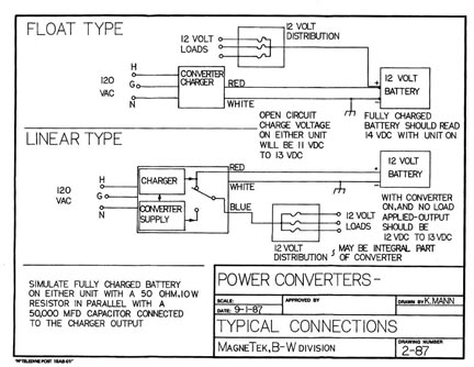
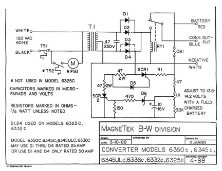
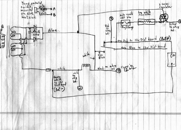
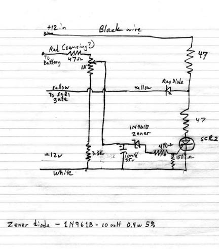
I was ultimately successful and the schematic I have included
is close enough, if not an exact rendering, of what is found in the Magnatek power
converter. I hope it helps others as it helped me. Now, with schematic in hand,
I returned to the project of repairing my converter.
CAUTION: When you decide to work on your power converter, be
sure you unplug your trailer’s power cable from the 120 volt AC mains. Once that
is done you can remove the screws holding the panel/cover onto the converter.
This will expose the transformer, diodes, solenoid, fan and battery charge board.
This solenoid is energized whenever the trailer is plugged into external AC power
and it allows the converter to send charging voltage to the trailer battery. Magnatek
chose to use a solenoid to activate a switch to perform this function rather than
use a relay. Why? I don’t know.
The following are steps required to remove all connections so you can pull
the whole power converter out to work on it:
-
Remove the 4 hex-head screws which hold the front board.
-
Remove the 2 hex-head screws holding the other board.
-
Remove the 12 volt wiring to the 12 v. distribution board – the white and
red wires have screws, the blue (12v) wire is attached with a screw and nut.
-
Open the cover to the 120v AC circuit breakers. (You did disconnect
the 120v AC didn't you?)
-
Remove the white wire which goes to the left side vertical screw strip.
-
Remove the black wire coming from the far right-hand circuit breaker.
-
Carefully feed the 2 AC and 3 DC wires from the top box so they are inside
the bottom power supply box. Now you can remove the power converter pieces.
-
With the power converter box on the workbench, remove 2 hex-head screws
holding the nylon posts which are holding the battery charger circuit board.
-
NOTE: With the power converter box on the workbench, the top cover can be
removed with 4 hex-head screws. This allows full access to the inside components.
The next step is to remove the board containing several electronic
parts including resistors, silicon controlled rectifier, Zener diode and a capacitor.
This board, on my unit, stood vertically and was attached to the right-hand wall
of the supply. NOTE: Do NOT attempt to pop the board off the nylon posts
where it is mounted. It will not come off and attempting to pop it loose will
result in a cracked board, which is made of rather fragile phenolic material.
Breaking that board can separate traces on the printed circuit board and you will
have additional problems. The board can be removed but only after the whole
box, holding the supply, is removed. (A word to the wise….. I hope..............
ask me how I know this...... No......... never mind.)
It is now that you must use your electronic trouble-shooting
skills to determine which component or components might be causing your problems.
That is rather difficult for me to tell you what might be causing your converter
to fail but, hopefully, this information and the schematic provided will allow
you to find it.
My problem turned out to be the large rectangular resistor
mounted with a pop rivet to the back panel of the box. The value was obscured
on mine but an ohmmeter check showed the value to be more than a mega ohm which
was much, much too high. I would guess that its true value should have been less
than an ohm but at a high power rating, perhaps 50–100 watts. It was here that
I had to do some guessing. Since this resistor is located in the line providing
charging current to the trailer battery, my guess is that its function is to drop
the load a bit when first connected to a battery which is totally discharged.
A fully discharged battery would place a tremendous temporary current load on
the power supply components and this resistor helps to protect things during
that initial surge.
After the repair was complete, I did some checking on the converter
to see just how much current was provided to a battery for charging and to see
whether the higher current stayed up at the high level or if it tapered off to
a trickle charge as this type of circuit should do. With a 0-3 amp meter in series
with the battery charging line, and using no extra resistance in the line (the
big white rectangular resistor was shorted to make zero ohms or there abouts),
I placed the charging circuit across a pair of 6 volt/7.7 AHr lead-acid batteries
which I had on hand. The ammeter started at just above 2 amps charging, then tapered
down to around 1.25 amps.
Then I tried it across a 12v/7 AHr lead-acid battery with was
already charged. The current started a just below an amp and within a minute,
dropped to about 200 milliamps or .2 amps. I say "about" because the ammeter
constantly wiggled the equivalence of .1 amp. I suspected that this might be caused
by the noticeable AC ripple in the DC line. After all, there is no filtering on
the rectified DC coming off the full-wave rectifier.
I located a 2 ohm, 50 watt resistor in my junk-box to replace
the defective one which had originally caused my problem. Placing the charger
wires across another charged 12v/7 AHr battery it started the charge current at
less than an amp. It also tapered down, within a couple of minutes, to about .2.amps……
a shaky .2 amps. The resistor did not even run warm but it had very little current
through it.
I finally found a .25 ohm/5 watt resistor and placed it in
the place of the original defective white rectangular unit pop riveted to the
back wall of the converter. I feared that the power rating on this resistor might
be too low but I have used this one for several months and it is holding up well.
I reassembled my converter by going in reverse with the steps
taken earlier to disassemble the unit. Everything went back together as easily
as it had come apart and I was a happy camper (so to speak). I hope, if you are
having problems as I was, that you can use some of this information and have as
much success as I did.
One additional piece of information – the fan which you hear
while the trailer is plugged into an external 120 v AC source, is actually running
on 120 v AC rather than 12v DC and is thermostatically controlled. A temperature
sensor is attached to the aluminum heat sink which holds the power diodes. When
they are doing their job and supplying 12 volt power to your trailer (not particularly
to the battery) those diodes will run hot and make the heat sink also quite hot.
The sensor turns on the fan which blows across the heat sink as well as our now
familiar power resistor. If you don’t hear the fan then the power converter is
not having to do much work and the fan gets to rest.
One other benefit on my converter is, I was able to clean up
all the dust and "grunge" around the fan and it has become much quieter. I still
hear it but nothing like it was previously.
Just as a final encouragement for you to try to repair your
own converter, when I looked up the replacement converter in a trailer accessories
catalog, the replacement unit was between $200 and $300. That was enough inducement
for me to attempt my own repairs.
Jim Pickett – K5LAD
jjpk5lad@...
Written June 29, 2002 ---- Updated
[ return to top ]

 Inside
the fold-down cover plate of the Electrical Load Center you will find two distinct
and separate electrical controls: the AC breaker side and DC fuse
or breaker side. Technically, there are no AC fuses, but rather breaker switches
which control the AC circuits found in the coach portion of the vehicle. The automotive
DC fuses or breakers control the DC circuits in the coach
portion of the vehicle.
Inside
the fold-down cover plate of the Electrical Load Center you will find two distinct
and separate electrical controls: the AC breaker side and DC fuse
or breaker side. Technically, there are no AC fuses, but rather breaker switches
which control the AC circuits found in the coach portion of the vehicle. The automotive
DC fuses or breakers control the DC circuits in the coach
portion of the vehicle.